3
4
4
Fit the rain shield 97B (supplied
with the previous stage) against
the window frame (95D) in the rear
right wall frame 95A. Fix in place with
four red BP screws.
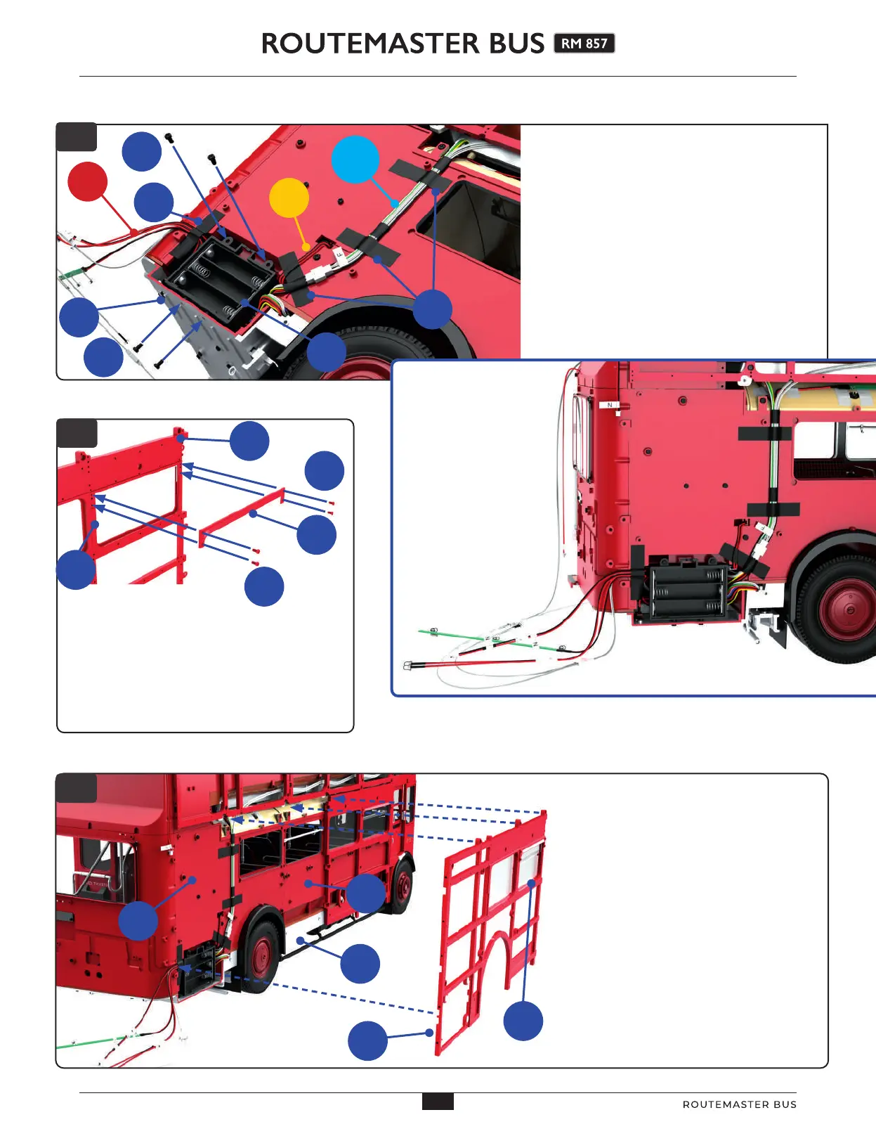
3
Fix the top edge of the battery box
56B in place with two JP screws
(supplied with stage 96). Use two more JP
screws to fix the battery box to the rear
platform 56A, inserting them from the
underside of the rear platform. Use four
strips of tape 96I to fix the ‘red’, ‘light blue’
and ‘yellow’ (53K) cables in place.
The inset below shows the finished
arrangement of the cables.
5
5
Position the right wall framework
95A aganst the rear right wall of the
model. The tabs along the top of part 95A
fit into recesses in the upper wall
framework. At the right rear corner, the
cables running across part 49C fit into a
recess in the framework 95A. At the base
of the framwork, screw holes align with
holes in the rear chassis frame 16A.
JP
x2
96I
96I
56B
Light
blue
group
Red
group
53K
BP
x2
BP
x2
48B
16A
95A
95D
49C
95A
95D
97B
JP
x2
56A
46
46
AGORAMODELS ROUTEMASTER BUS