2
2
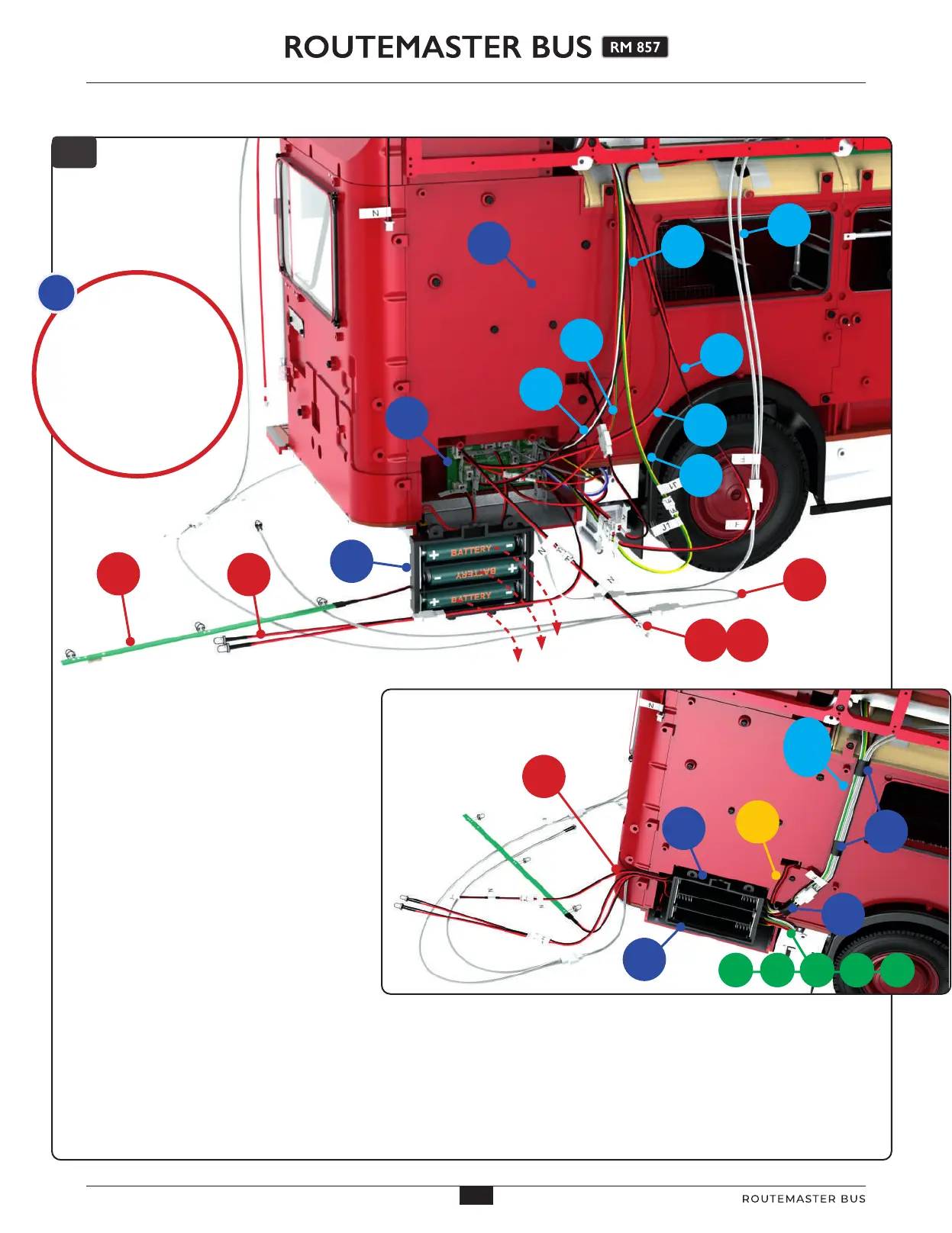
Group the cables together into strands
as follows:
•
Take the cables (labelled above in light
blue) coming down from the upper deck
55H (J), 56C (N), 71A (H), 71B (J1), 71C (M),
71D (L) and 80J (F) and arrange them the
wall panel 49C. When you are happy with
the fit, wrap strips of tape 96I around them
to hold them together (inset).
•
Group together the cables (labelled in
green, inset) 38N (B), 41K (C), 43D (D),
37D (E) and 38M (A). Arrange them
together so that they come from beneath
the model to the circuit board.
•
Group together cables (labelled in red)
72B (O), 71E (F), 72C (G) and 56C (N,
connected to 89E), bringing them together
through the recess at the rear of the model
(inset).
•
Note the position of cable 53D (K),
labelled in yellow in the inset.
•
Remove the batteries from the battery box 56B (red
dotted arrows, top diagram).
•
Arrange any excess length of the grouped cables
around or across the circuit board. Position the battery
box 56B in front of the circuit board so that the holes at
the top are aligned with the screw holes in part 57D.
We have
given each group
of cables a colour,
and labelled them in
the diagrams with the
colour. The colours of the
labels/groups are not
related to the colours
of the cables.
4
71A
55H
80J
56C
71C
71B
49C
71D
57D
56B
72B
72C
71E
Light
blue
group
38M
37D
43D
41K
38N
Red
group
56C
53K
89E
57D
96I
96I
56B
45
45
AGORAMODELS ROUTEMASTER BUS
46
AGORAMODELS ROUTEMASTER BUS