31-01
28-01
31-01
PM
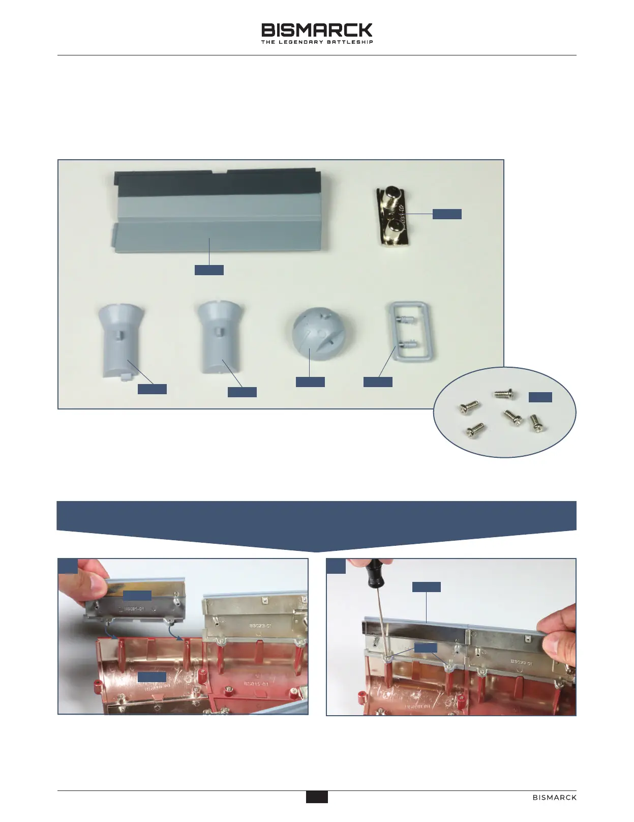
01. FITTING THE UPPER PORT HULL SECTION
STAGE 31
HULL SECTION AND SECOND
RANGEFINDER
01
Place the hull assembly on your worksurface. Position
the upper port hull section 31-01 on the structure so
that the two tabs fit over the screw sockets in part
28-01, as indicated by the arrows.
Fix the hull section 31-01 in place with two of the
PM screws.
02
PM
31-02
31-03
31-0631-05
31-04
31-01
COMPONENTS CHECKLIST
31-01: Upper port hull
section
31-02: Connector
31-03: Half director
tower
31-04: Half director
tower
31-05: Rangefinder
dome
31-06: Two rangefinder
arms
PM: Five 2 x 4mm PM
screws
36
36
AGORAMODELS BISMARCK
PB
AGORAMODELS BISMARCK