23-01
31-02
31-04
31-03
31-01
31-02
PM
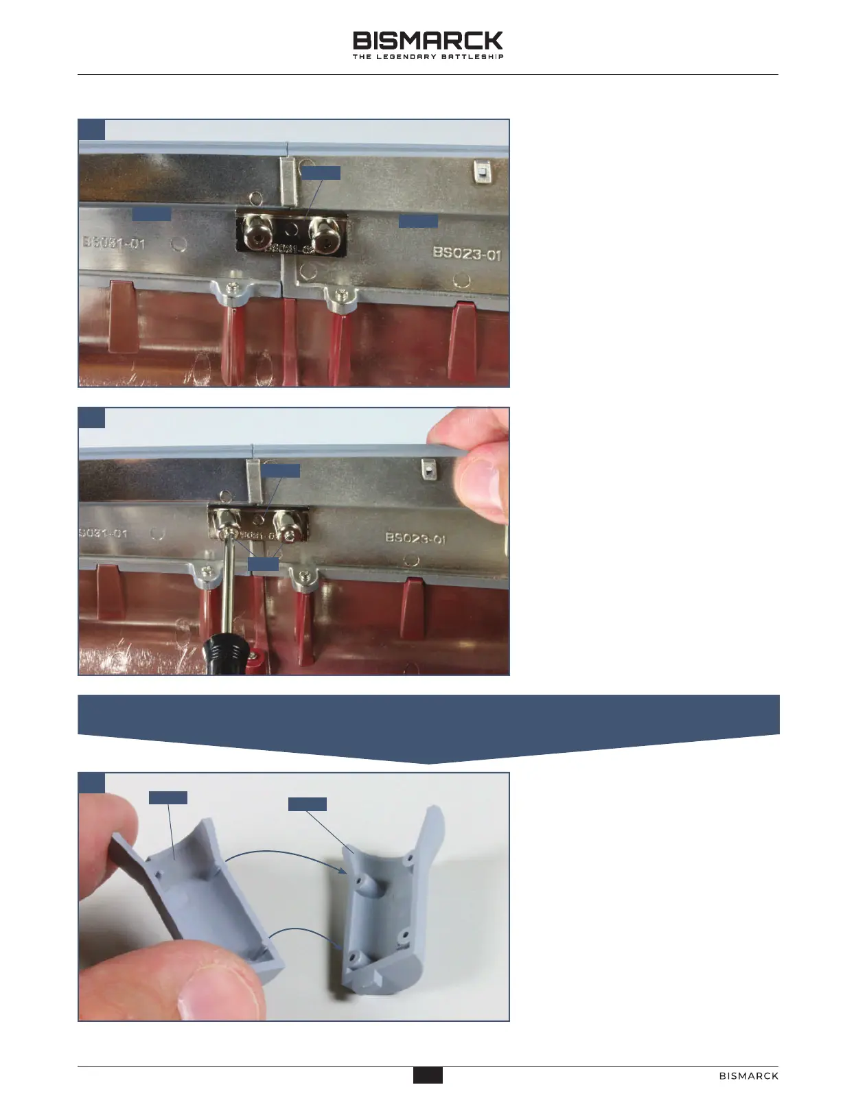
Position the connector 31-02 across the
join between the upper hull sections
31-01 and 23-01 so that the sockets on
part 31-02 fit over the raised screw
sockets on parts 31-01 and 23-01.
Fix the connector 31-02 in place with
two PM screws.
Check the fit of the two halves of the
director tower 31-03 and 31-04. Apply
a little superglue to the pegs on part
31-04 and glue them into the sockets
on part 31-03.
03
04
02. ASSEMBLING AND FITTING THE FORWARD PORT RANGEFINDER
01
37
37
AGORAMODELS BISMARCK
PB
AGORAMODELS BISMARCK