pg 11
Installation continued...
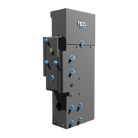
attached to each end of the gate by
using the gate brackets and chain
bolts as shown at left. If the gate frame
is 2" X 2" square tube, the gate
brackets may bolted to the gate using
the square u-bolts as shown. For
round tubular frames, use the supplied
round u-bolts for attaching the brack-
ets. In this case use the self tapping
screw which prevents the bracket from
shifting. For irregular sized gate
frames, the gate brackets should be
welded to the gate. Attach the chain
ends with master links and tension the
chain by tightening the chain bolt nuts.
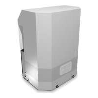
m The limits of travel determine
where the gate stops in both the open
and closed positions. These limits may
be adjusted very closely without any
power to the gate operator. Before
making these adjustments, the gate
operator may be put into manual
release by turning the manual release
key switch as shown at left. This
allows the gate to be pushed manually
in either direction. Be careful not to run
the limit nuts past the limit switches as
this may cause damage to the
switches.
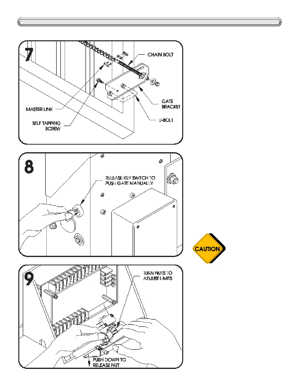
m The limits of travel are ad-
justed by positioning the limit nuts
against the limit switches (pressing in
the switch) while the gate is open or
closed. To adjust the limit nuts, first
push down on the limit nut guide plate.
This allows the limit nuts to be freely
spun up or down the screw. One limit
nut should press in one limit switch
when the gate is open, and the other
nut should press in the other switch
when the gate is closed. When
finished, be sure that the limit guide
plate firmly engages both limit nuts.
DO NOT ADJUST THE
LIMITS WHILE
THE POWER IS ON
 Loading...