Do you have a question about the Ahlborn ALMEMO 2590-3S and is the answer not in the manual?
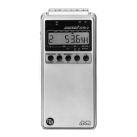
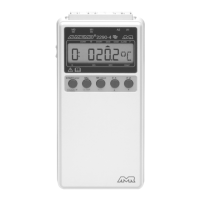
Details of input channels for ALMEMO sensors.
Ports for connecting output modules and peripherals.
Connection for mains adapter or external DC voltage.
Indicator for low power consumption mode.
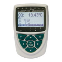
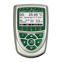
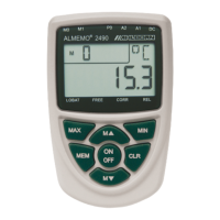
Screen for displaying measurements and menus.
Buttons for device control and menu navigation.
Location for 3 AA alkaline batteries.
Details of the manufacturer's guarantee and terms.
List of items included with the measuring instrument.
Safe handling and disposal of batteries.
Important considerations for optimal device operation.
Overview of device capabilities, sensors, and software.
Supported sensor types and measurement ranges.
Creating channels for calculated values like averages.
Naming and adjusting measured values.
Setting thresholds for alerts and control.
Protecting sensor configuration from unauthorized changes.
How to perform measurements and get data out.
Starting, stopping, and timing measurement processes.
Memory, numbering, and control for data logging.
Connecting sensors and providing power.
Accessing menus, display settings, and basic configurations.
Configuring cycle timers, output formats, and starting measurements.
Handling data memory and output to external devices.
Using and checking battery status for device power.
Connecting to AC power or external DC sources.
Details on providing power to connected sensors.
How to connect ALMEMO® sensors and custom sensors.
Understanding input sockets and channel assignments.
Ensuring electrical isolation for accurate measurements.
Understanding the LCD screen and menu structure.
Interpreting displayed values and system status indicators.
Using F1, F2 and navigation keys for operations.
Activating functions and entering data via the keypad.
Overview of measuring and programming menus.
Accessing device details and web support.
Viewing current measurements and sensor status.
Navigating through available measurement channels.
Adjusting zero points and applying compensation.
Setting a reference point for deviation measurements.
Calibrating dynamic pressure and chemical sensors.
Correcting values based on environmental conditions.
Calculating the difference between two sensor inputs.
Overview of all active measuring channels and values.
Creating custom display layouts for specific applications.
Storing and recalling peak, minimum, and single recorded values.
Calculating averages using various methods like sliding or time-based.
Calculating flow rates using velocity and cross-section data.
Advanced flow measurement across multiple points.
Calibrating sensors using two points and applying scaling factors.
Managing internal and external memory for data recording.
Using MMC cards for extended data storage.
Configuring the device's real-time clock.
Performing single or cyclic data acquisition and output.
Setting scan modes, rates, and memory activation.
Controlling measurement processes via time or duration.
Choosing active measurement channels for configuration.
Assigning alphanumeric names to measurement points.
Setting averaging methods and protecting configurations.
Defining thresholds and applying calibration factors.
Adjusting zero-point, gain, and display units.
Configuring the appropriate range for different sensors.
Using channels for derived measurements like humidity variables.
Advanced calibration and linearization features.
Configuring alarm actions, print factors, and relays.
Scaling analog outputs and monitoring sensor supply.
Selecting output data and using reference channels for calculations.
Enabling additional sensor-specific functions.
Setting device designation, language, illumination, and contrast.
Configuring serial interfaces, baud rates, and network settings.
Adjusting for atmospheric pressure and temperature.
Configuring alarm hysteresis and software options.
Information on interface cables and their use.
Connecting and configuring output modules.
Setting up analog signal outputs for recording or display.
Diagnosing and resolving operational issues and errors.
Troubleshooting interface communication problems.
EMC standards and precautions for device operation.
Detailed technical parameters of the ALMEMO® 2590.
Summary of device models and available accessories.
| Brand | Ahlborn |
|---|---|
| Model | ALMEMO 2590-3S |
| Category | Measuring Instruments |
| Language | English |