Do you have a question about the Ahlborn ALMEMO 2590-4S and is the answer not in the manual?
Details on inputs for ALMEMO® sensors and additional channels.
Explains V24, USB, Ethernet, and other interface outputs.
Connection for mains adapter or DC voltage supply.
Indicates the device's sleep mode status.
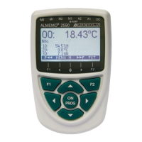
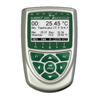
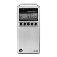
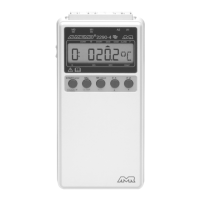
Describes the 7-line display and softkey layout.
Explains the function of ON/PROG, F1, F2, and cursor keys.
Location for 3 AA alkaline-manganese batteries.
Details the 2-year guarantee and its exclusions.
Lists the items included with the ALMEMO® 2590.
Proper handling and disposal guidelines for batteries.
Advises on condensation, mains voltage, sensor power, and static electricity.
Overview of ALMEMO® system capabilities, sensors, and device features.
Details on evaluating sensors, channel navigation, and data output.
Explains recording, starting/stopping operations using various triggers.
How to select and view sensor parameters for input channels.
Assigning alphanumeric names to measuring points for identification.
Defining averaging modes for measured values.
Protecting sensor parameters with a locking level.
Setting maximum/minimum limits and configuring alarm actions.
Adjusting measured values using base, factor, and exponent.
Applying zero-point and gain corrections for sensor accuracy.
Connecting sensors and providing power via batteries or mains.
Switching on, display illumination, and navigating menus.
Configuring saving, cycle timers, output formats, and starting/stopping.
Outputting memory data, clearing memory, and important key functions.
Using batteries and monitoring supply voltage status.
Connecting the device to the mains adapter.
Connecting external DC power sources.
Details on the 9V sensor supply and available options.
Procedures for turning the device on/off and reinitializing.
How sensor programming and device parameters are stored.
Connecting ALMEMO® sensors and using external sensors.
Allocating channels M0-M4 and using additional sensor channels.
Explains the 4 internal channels and their default/programmable uses.
Ensuring electrical isolation between sensors, power, and peripherals.
Overview of the LCD display and methods for menu selection.
Interpreting displayed values and status symbols.
Explains the operation of softkeys and cursor keys within menus.
Activating or programming specific functions within menus.
Entering alphanumeric and numeric data using the keypad.
Lists measuring, function, and programming menus, and how to access them.
Obtaining device information and accessing online help.
The default menu showing measuring point, value, and associated functions.
Navigating through active measuring points.
Performing zero-point and gain adjustments for sensor accuracy.
Zeroing the measured value to establish a reference.
Performing zero-point adjustment for dynamic pressure sensors.
Adjusting chemical sensors for zero-point and gain.
Compensating measurements based on temperature deviations.
Compensating measurements based on atmospheric pressure.
Compensating thermocouple measurements using cold junction temperature.
Calculating the difference between two measuring points.
Overview of all measuring points with values and functions.
Configuring a custom menu for data logging tasks.
List of available functions for user menu configuration.
Steps to configure user menus using AMR-Control software.
Acquiring and storing maximum, minimum, and individual measured values.
Overview of averaging modes for processing measured values.
Smoothing fluctuating values using a sliding average window.
Calculating averages from individual manual measuring operations.
Determining average values over a specified duration.
Acquiring hourly or daily averages at cyclic intervals.
Determining average values across multiple measuring points.
Calculating volume flow from average velocity and cross-section.
Calculating average velocity in flow channels using array measurements.
Correcting errors using two calibration points and setpoints.
Scaling sensor signals to display physical variables using base and factor.
Functions for acquiring and recording measured values.
Details on the internal 59-KB EEPROM for data logging.
Using external MMC cards for expanded data logger capacity.
Setting and using the device's real-time clock for data logging.
Initiating single scans for current values and setting output format.
Programming cycle and output format for continuous recording.
Assigning numbers to identify measurement series.
Checking memory status, outputting, and clearing memory contents.
Setting general conditions for measuring point scans.
Activating cyclic saving to memory and setting recording speed.
Selecting between Normal, Sleep, Monitor, and Fail-safe modes.
Configuring the device for energy-saving long-term monitoring.
Monitoring data loggers cyclically via computer.
Ensuring continuous scanning during computer failures.
Defining print layouts (List, Columns, Table) for data output.
Adjusting scan rate and enabling continuous scanning.
Understanding available recording time based on memory and settings.
Methods for starting and stopping measuring operations automatically or manually.
Choosing and viewing sensor parameters for a specific input channel.
Assigning descriptive alphanumeric names to measuring points.
Setting the averaging mode for measured values.
Protecting sensor programming settings with a locking level.
Programming maximum and minimum limit values for alarms.
Adjusting measured values and setting decimal point positions.
Applying zero-point and gain corrections to sensor readings.
Replacing default units with custom two-character units.
Setting the appropriate measuring range for sensors.
Using function channels for measured value processing and results.
Using special ranges, linearization, and multi-point calibration.
Adjusting data recording speed by setting output frequency.
Configuring relay assignments and actions for limit value events.
Scaling analog outputs and display ranges.
Monitoring and setting the minimum required sensor supply voltage.
Programming output functions to process specific values (max, min, avg).
Defining reference channels for function channel calculations.
Using a second reference channel or multiplexer for input selection.
Activating additional functions specific to sensors using element flags.
Entering a text string for device identification in printouts and lists.
Choosing the display language for menus and printouts.
Adjusting display brightness and contrast levels.
Configuring serial interfaces, device addresses, and network settings.
Setting communication parameters for interfaces.
Setting compensation parameters for specific sensors.
Setting hysteresis for alarm triggers.
Configuring various software options and parameters.
Information on ALMEMO® data cables and connection modules.
Connecting relay modules for peripheral control and trigger inputs.
Configuring analog output signals for recording.
Troubleshooting steps for display issues, unresponsive keys, and power.
Diagnosing and correcting issues with inaccurate readings.
Checking cabling and sensors for intermittent or frozen operation.
Troubleshooting communication problems via the interface.
Details on the device's compliance with EMC directives and standards.
Precautions regarding high-voltage cables and electromagnetic fields.
Specifications for measuring inputs, outputs, power, and housing.
Summary of ALMEMO® 2590 models and available accessories.
Contact details for support or further information.
| Type | Data logger |
|---|---|
| Input Channels | 4 |
| Measurement Channels | 4 |
| Measurement Rate | up to 10 Hz |
| Voltage Range | ± 10 V |
| Current Range | 0 to 20 mA |
| Frequency Range | 0 to 10 kHz |
| Display | LCD |
| Temperature Range | -200 to 1370 °C |
| Sampling Rate | 10 Hz |
| Communication Interface | RS-232, USB |
| Power Supply | Battery |
| Operating Temperature | -20 to 50 °C |
| Measurement Range | varies by sensor type |