Do you have a question about the Ahlborn ALMEMO 710 and is the answer not in the manual?
Details the manufacturer's guarantee period and conditions for product coverage.
Lists the items included in the ALMEMO® 710 package upon delivery.
Provides guidance on the proper disposal of the device and its accessories.
Offers specific advice for using the device in various conditions and with sensors.
Explains the correct procedures for charging and handling the rechargeable battery pack.
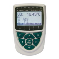
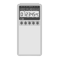
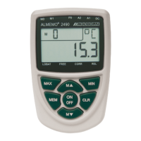
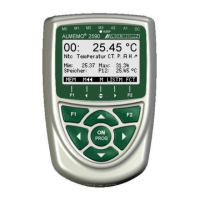
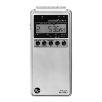
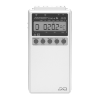
Describes the key features, sensors, and operational modes of the ALMEMO® 710 data logger.
Details battery life, charging, and monitoring of power supply status.
Explains how to power the device using the mains adapter for operation or charging.
Describes connecting an external DC voltage source for device power.
Explains the sensor supply voltage configuration and availability.
Covers how to turn the device on/off and perform a system reinitialization.
Details how data and settings are buffered and retained intact.
Describes the characteristics and intelligence of standard ALMEMO® V5 and V6 sensors.
Explains the features and capabilities of autonomous ALMEMO® D6 sensors.
Details the enhanced properties of autonomous ALMEMO® D7 sensors.
Explains the 10 input sockets and the numbering scheme for channels.
Discusses the importance and implementation of electrical isolation for measurements.
Describes the function of the device's dedicated touchkeys.
Explains how to navigate and select different applications on the main screen.
Details the use of superordinate keys for controlling measuring operations.
Explains the meaning of the various status LEDs on the device.
Describes the symbols used to indicate battery and memory status.
Explains how measured values and parameters are displayed with symbols.
Guides the user on how to enter alphanumeric and numerical data.
Details how measured values are acquired, recorded, and output.
Explains how to add comments text to memory configurations.
Describes the different scan modes for autonomous or computer-controlled operation.
Covers various methods for starting and stopping measuring operations.
Explains how to check memory status and delete recorded data.
Details how to output recorded data from the device memory.
Provides an overview of all measured values and parameters for connected channels.
Explains how to display measured values using a bar chart format.
Describes how to display measured values graphically using line graphs.
Explains how to create and use custom menus for data display and functions.
Details how to view and process measurements from individual channels.
Explains methods for correcting and compensating measured values for accuracy.
Allows selection and configuration of sensors, ranges, and calibration data.
Covers detailed settings for each measuring channel, including designation and smoothing.
Explains settings related to display options like scaling for charts and graphs.
Provides access to data logger configuration parameters already described in Chapter 10.
Describes the configuration of output modules for analog or digital data and alarm signals.
Covers communication, macros, operating parameters, and general device settings.
Explains how to enable/disable access to menus or functions using a password.
Details battery capacity, charging, and sensor voltage settings.
Provides information on memory status, total size, free space, and deletion.
Displays device type, serial number, software versions, and contact information.
Guides the user through setting up data acquisition tasks and parameters.
Assists in calculating scaling parameters for displaying sensor signals as physical quantities.
Helps perform a two-point adjustment for accurate sensor calibration.
Explains various modes for averaging measured values to smooth data.
Guides on calculating volume flow from velocity and cross-section area.
Details the process for determining the thermal coefficient using temperature sensors.
Explains the calculation of wet-bulb globe temperature for workplace assessment.
Lists detailed technical specifications and data for the ALMEMO® 710.
An alphabetical index of terms and their corresponding page numbers.
Provides contact details for Ahlborn Mess- und Regelungstechnik GmbH.
| Data Logger | Yes |
|---|---|
| Display | LCD display |
| Interface | USB, RS232 |
| Power Supply | Battery or external power supply |
| Input Types | Voltage, current, resistance, temperature |
| Measurement Range | Depends on sensor used |
| Accuracy | Depends on sensor used |
| Resolution | Depends on sensor used |
| Sampling Rate | Up to 10 Hz |