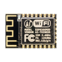
The ESP-01/07/12 Series Modules are cost-effective Wi-Fi SOC modules developed by Ai-Thinker Inc, designed to add networking capabilities to existing devices or to build standalone network controllers. These modules support the standard IEEE802.11 b/g/n protocol and have a built-in complete TCP/IP protocol stack. Ai-Thinker Technology provides comprehensive hardware and software reference programs to shorten product development cycles and reduce costs.
Function Description
The modules serve as a core component for Wi-Fi connectivity in various applications. They can be used as the main application processor due to their low-power 32-bit CPU, clocked at up to 160MHz. The integrated Wi-Fi MAC/BB/RF/PA/LNA ensures robust wireless communication. The modules support multiple sleep modes, with deep sleep current as low as 20uA, making them suitable for power-sensitive applications. An embedded Lwip protocol stack facilitates network communication. They support STA/AP/STA + AP work modes and Smart Config/AirKiss key distribution networks for easy setup. Users can quickly utilize general AT commands or develop custom applications using the SDK. Firmware upgrades are supported both locally via serial port and remotely (FOTA).
Important Technical Specifications
General:
- CPU: Low-power 32-bit CPU, up to 160MHz.
- Wi-Fi Protocol: IEEE802.11 b/g/n.
- Protocol Stack: Built-in complete TCP/IP protocol stack, embedded Lwip protocol stack.
- Interfaces: UART, GPIO, IIC, PWM, ADC, HSPI.
- Sleep Modes: Multiple sleep modes, deep sleep current as low as 20uA.
- Work Modes: STA/AP/STA + AP.
- Configuration: Smart Config/AirKiss key distribution network.
- Serial Port Rate: Up to 4Mbps.
- Development: General AT commands, SDK secondary development.
- Firmware Upgrade: Serial local upgrade, remote firmware upgrade (FOTA).
- ADC: Built-in 10-bit high precision ADC, input voltage range 0~1V.
Module Dimensions (Length x Width x Height, in mm):
- ESP-01/ESP-01S: 24.7 x 14.4 x 11.0
- ESP-01M: 18 x 18 x 2.8±0.2
- ESP-01F: 11 x 10 x 2.0±0.2
- ESP-07: 21.2 x 16.0 x 3.0±0.2
- ESP-07S: 17.0 x 16.0 x 3.0±0.3
- ESP-12F: 24.0 x 16.0 x 3.0±0.2
- ESP-12S: 24.0 x 16.0 x 3.0±0.2
Electrical Characteristics:
- Supply Voltage:
- Maximum Ratings: +3.0V to +3.6V
- Suggested Working Environment: 3.0V to 3.6V (Typical 3.3V)
- Storage Temperature: -40°C to 90°C
- Operating Temperature: -20°C to 85°C (Typical 20°C)
- Digital Port Features (VDD = 3.3V, Temperature 20°C):
- Input Logic Level Low (VIL): -0.3V to 0.25 * VDD
- Input Logic Level High (VIH): 0.75 * VDD to VDD + 0.3V
- Output Logic Level Low (VOL): N to 0.1 * VDD
- Output Logic Level High (VOH): 0.8 * VDD to N
Power Consumption (at antenna interface without SAW filters, 90% duty cycle for transmit data):
- Transmit 802.11b, CCK 11Mbps, POUT = +17dBm: 170mA
- Transmit 802.11g, OFDM 54Mbps, POUT = +15dBm: 140mA
- Transmit 802.11n, MCS7, POUT = +13dBm: 120mA
- Receive 802.11b, packet length 1024 bytes, -80dBm: 50mA
- Receive 802.11g, packet length 1024 bytes, -70dBm: 56mA
- Receive 802.11n, packet length 1024 bytes, -65dBm: 56mA
- Modem-Sleep: 20mA (CPU active, WiFi Modem off during no data transmission)
- Light-Sleep: 2mA (CPU suspended, WiFi Modem off during no data transmission)
- Deep-Sleep: 20uA (WiFi connection not maintained, e.g., sensor applications)
- Power Off: 1uA
RF Parameters:
- Transmit Power:
- 802.11b@11Mbps: 14-18dBm (Typical 16dBm)
- 802.11g@54Mbps: 12-16dBm (Typical 14dBm)
- 802.11n@HT20, MCS7: 11-15dBm (Typical 13dBm)
- Receive Sensitivity:
- DSSS, 1 Mbps: -95dBm
- CCK, 11 Mbps: -80dBm
- 6 Mbps (1/2 BPSK): -88dBm
- 54 Mbps (3/4 64-QAM): -70dBm
- HT20, MCS7 (65 Mbps, 72.2 Mbps): -67dBm
Package Type:
- ESP-01/ESP-01S: DIP-8
- ESP-01M: SMD-18
- ESP-07/ESP-07S: SMD-16
- ESP-12F: SMD-22
- ESP-12S: SMD-16
Flash Size: 8Mbit (ESP-01/01S/01M/07/07S), 32Mbit (ESP-12F/12S)
Antenna Type: PCB (ESP-01/01S/01M/01F/07/07S/12F/12S), Ceramic IPEX (ESP-07/07S/12S)
Available IO: 2 (ESP-01/01S), 11 (ESP-01M), 9 (ESP-07/07S/12F/12S)
Usage Features
The modules are designed for ease of integration and use in various applications:
- Typical Applications: Household appliances, home automation, smart sockets/intelligent lights, mesh networks, industrial wireless control, wearable electronics, infant monitors, wireless location sensing devices, security ID tags, IP cameras, and sensor networks.
- Power Supply: It is recommended to use two dry batteries or a 3.3V LDO after conversion. Direct USB to TTL 3.3V or 5V power supply is not recommended.
- GPIO Level Conversion: Reference designs are provided for interfacing with 3.3V and 5V systems using transistors.
- Automatic Download: A reference design is available for automatically entering download mode, simplifying firmware flashing.
- AT Command Set: The modules come with factory default AT firmware (baud rate 115200). Basic AT commands like
AT (test), AT+GMR (firmware version), AT+RST (soft restart), and AT+RESTORE (factory reset) are available.
- TCP/UDP Communication: Detailed examples are provided for setting up TCP servers and clients, and UDP communication between modules.
- SDK Development: Support for secondary development using the SDK is available, with resources for building the development environment.
Maintenance Features
- FCC Compliance: The modules comply with Part 15 of the FCC Rules. Changes or modifications not expressly approved by the responsible party could void user authority to operate the equipment.
- Interference: The device must accept any interference received and not cause harmful interference.
- Installation: If the FCC ID is not visible when the module is installed inside another device, the host device must display a label referring to the enclosed module (e.g., "Contains FCC ID:2AHMR-ESP01M").
- Radiation Exposure: The equipment must be installed and operated with a minimum distance of 20cm between the radiator and the user's body.
- OEM Installation: The module is limited to OEM installation only. The OEM integrator is responsible for ensuring the end-user has no manual instruction to remove or install the module.
- Mobile Application: The module is limited to installation in mobile applications.
- PCB Antenna Design: Guidelines are provided for optimal PCB antenna placement to achieve the best RF performance. This includes placing the module along the edge of the PCB board with the antenna outside the frame, or along the board with the bottom hollowed out, or along the board with the bottom not copper.
- Peripheral Routing: For applications requiring high power and EMI characteristics, it is recommended to connect 10 to 100 ohms in series on digital I/O lines to suppress overshoot, smooth signals, and prevent electrostatic discharge (ESD).
- Reflow Soldering: A reflow oven temperature curve is provided for proper soldering, with specific ramp-up, preheating, reflow, and cooling down zones. Peak temperature is recommended between 235°C and 250°C (preferably <245°C) for 30-70 seconds.
- Troubleshooting:
- Garbage Instructions on Power On: This can occur if a 40MHz crystal is used with a default baud rate of 115200, as the UART0 baud rate becomes 74880. Using a serial interface assistant configured to 74880 baud rate can resolve this.
- Shielding Garbled Output: The U0TXD default system printing can be redirected to GPIO15 (U0TXD) and GPIO13 (U0RXD) using
system_uart_swap() function in user_init().
- Burning Issues: Refer to the provided wiki link for download instructions and ensure the module is in download mode before burning firmware.