Need help?
Do you have a question about the aiko AIKO-A MAH54Mw Series and is the answer not in the manual?
Identifies module type, power, and serial number for tracking and verification.
Details how AIKO modules are connected in series for optimal electrical configuration.
Outlines essential safety precautions for handling and installing PV modules.
Provides critical guidelines to prevent electrical accidents during installation and operation.
Specifies safe practices for physically handling modules to prevent damage and injury.
Covers fire protection requirements and recommendations for module installation.
Guidelines for safely receiving and unloading PV modules from transport.
Best practices for transporting modules to the installation site without damage.
Recommendations for storing modules to maintain their quality and prevent damage.
Specifies suitable environmental conditions for module installation and operation.
Guides on choosing the optimal tilt angle for maximum solar energy capture.
Outlines general principles for secure and compliant mechanical mounting of modules.
Details specific methods for mounting AIKO single glass PV modules.
Explains how to use pressure clamps for module mounting, including specifications.
Illustrates clamp mounting positions and load capacities for different module sizes.
Describes the procedure for securing modules using bolts through mounting holes.
Shows bolt mounting configurations and load data for module frames.
Details mounting requirements for AIKO modules on single-axis tracking systems.
Presents the key electrical characteristics and performance parameters of AIKO modules.
Guides on selecting and connecting appropriate cables and connectors for PV systems.
Provides instructions for handling and mating module connectors correctly.
Recommends methods and best practices for cleaning PV modules to maintain efficiency.
Lists visual inspection points for module integrity and potential defects.
Outlines periodic checks for connectors and cables to ensure system reliability.
Provides guidance on how to contact AIKO for technical assistance and support.
This document serves as the AIKO PV Module Installation Manual for Single Glass Modules, providing comprehensive guidelines for their safe and effective deployment.
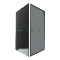
AIKO PV modules are designed to convert sunlight into DC electrical energy. They are certified according to IEC-61215 and IEC-61730 standards, boasting a safety class II and fire class rating C. These modules are intended for various solar energy applications, contributing to sustainable power generation. The junction box, an integral part of the module, houses connected cables and IP68 connectors, ensuring robust and weather-resistant electrical connections. Modules are equipped with both positive and negative PV wires, facilitating series connections with adjacent modules. The design incorporates an anodized anticorrosive aluminum alloy frame, which acts as a rigid support and requires proper grounding to ensure safe operation and protection against lightning and electrostatic damage.
The installation process requires adherence to local laws and regulations, including electrical and construction codes, which may vary by location and system type (e.g., rooftop installations, DC or AC systems). Modules should be installed by qualified personnel familiar with mechanical and electrical requirements, capable of identifying and mitigating potential hazards like electrical shock.
Installation Conditions: Modules are recommended for installation in environments with temperatures ranging from -20°C to 50°C, with extreme conditions tolerated from -40°C to 85°C and humidity below 85%RH. They are designed to operate up to 2000 meters above sea level. Critical considerations include avoiding locations prone to flooding, open flames, or flammable materials. For installations near seashores (within 50m to 500m), the frame and related components must undergo anti-corrosion treatment. Rooftop installations necessitate a safe working area around the module array and a thorough assessment of roof loads by construction experts.
Optimal Performance: Modules should be positioned to receive adequate sunlight, avoiding partial or complete shading from trees, buildings, or other obstructions. Proper ventilation is crucial for heat dissipation, as poor airflow can reduce output power. The tilt angle of PV modules, defined as the angle between the module surface and the horizontal ground, should be selected based on local conditions to maximize annual energy generation. All modules within an array should have the same orientation and angle to prevent output mismatch and maintain system efficiency. AIKO recommends an installation angle of not less than 10 degrees, considering factors like irradiance, wind speed, and snow load.
Mechanical Installation: Modules can be mounted using pressure clamps or bolts. The mounting system must be made from anticorrosive, ultraviolet-resistant materials and should be tested by a third-party institution for static mechanical analysis. In areas with heavy snowfall, the mounting system's height should be adjusted to prevent snow from covering the module's lower edge. A minimum gap of 10cm between the module frame and the roof is recommended for air circulation. Adjacent modules should maintain a minimum mounting distance of 10mm. Pressure clamps should be at least 50mm in length and 3mm in thickness, with an overlap distance of 7mm to 10mm between the clamp and the module frame. At least four clamps per module are required, with six clamps recommended for areas with high wind or snow loads. For bolt mounting, modules come with 4 or 8 mounting holes matching M8 bolts. The tightening torque for M8 nuts and bolts should be between 16-20 Nm.
Electrical Installation: The electrical performance parameters are detailed in the product specification, based on standard test conditions (STC) of 1,000 W/m² irradiance, 25°C cell temperature, and AM1.5. The maximum system voltage is 1,500 V. In series connections, the string voltage is the sum of individual module voltages, while in parallel connections, the current is the sum of individual module currents. Modules in the same string must have the same product code and nominal power. Overcurrent protection devices are necessary if reverse current exceeds the maximum fuse current. The string voltage must not exceed the maximum voltage the system can withstand, calculated using the open circuit voltage, thermal coefficient, and lowest ambient temperature.
Cables and Connections: Specialized solar wires with a cross-sectional area of 4 mm² are recommended, temperature-resistant to at least 90°C, and UV resistant. The minimum bending radius for cables is 43mm. Cables should be routed in appropriate conduits away from water-prone areas. Connectors must be kept dry and clean, with nuts tightened before connection. Avoid connecting wet or abnormal connectors. Once installed, modules should be connected promptly to prevent water vapor and dust ingress into the connectors. Electrical connections must be secure to prevent arcing and shocks. Different models of connectors should not be mated.
Grounding: Module frames must be grounded using grounding screws, flat washers, puncture gaskets, and copper grounding wires. These components should be stainless steel, except for copper wires. Grounding conductors connect to an appropriate grounding electrode. Grounding holes (4.2 mm) on the module frame are used for this purpose, with M4x12 mm grounding bolts, M4 nuts, star washers, and flat washers recommended. The tightening torque for grounding bolts should be 3-7 Nm, using 4 mm² copper wires. Unused module mounting holes can also be utilized for grounding.
Regular inspection and maintenance are crucial for the longevity and performance of AIKO PV modules.
Cleaning: The power output of modules can be reduced by dust and other shadings, necessitating immediate cleaning. The cleaning frequency depends on the level of dirt accumulation. Modules installed at an adequate tilt angle can be naturally cleaned by rainwater.
Visual Checks: Preventive examinations every six months are recommended to identify visual defects such as:
Checks of Connectors and Cables: Preventive examinations every six months should also include checking:
Technical Support: For technical support, users should collect evidence of the issue, including photos and measurements. They should also be prepared to provide the purchase invoice and module serial number, and contact their installer.
 General
| Frame | Anodized Aluminum Alloy |
|---|---|
| Connector | MC4 Compatible |
| Temperature Coefficient of Isc | 0.05%/°C |
| Maximum System Voltage | 1500V |
| Junction Box | IP68 rated |


 To Next Page