Do you have a question about the aiko AIKO-A450-MAH54Mb and is the answer not in the manual?
Explains the series connection modes for AIKO photovoltaic modules via junction boxes.
Covers AIKO PV module compliance with standards and general safety precautions during installation.
Details critical electrical safety provisions to prevent accidents during PV module installation and operation.
Outlines safe handling, installation, and operational procedures for AIKO PV modules to prevent damage and injury.
This document serves as an installation manual for photovoltaic (PV) modules manufactured by Shenzhen Aiko Digital Energy Technology Co., Ltd., referred to as "Aiko." It provides essential information for the safe and proper installation and routine maintenance of these modules. The manual emphasizes adherence to all specified safety precautions, local laws, and regulations throughout the product's lifecycle.
The PV modules are designed for various applications, including building roof installations and vehicle-mounted systems. They are intended for use in systems with DC 50V or above 240W, where the public may come into contact with them. The modules are classified as Class II for safety and Class C for fire protection, with a fire type classification of Type 4 based on construction and fire performance.
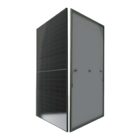
The Aiko PV modules are designed to convert sunlight into direct current (DC) electricity. They are a core component of solar power systems, generating power that can be used or stored. The modules are constructed with an aluminum alloy frame, photovoltaic glass, film, ABC cells, backsheet, and silicon, all enclosed within a junction box. The junction box contains electric cables and connectors for electrical integration into a larger system. Mounting holes are provided for secure attachment to support structures, along with ground grounding holes and water leakage holes. Each module is equipped with a nameplate detailing its electrical performance parameters and certifications, a unique serial number for identification, and, if applicable, a current grading label for differentiation based on rated current.
The installation process requires professional skills and knowledge, and only qualified personnel familiar with mechanical and electrical system requirements should perform installation and maintenance. The manual outlines specific wiring modes for series connections, with diagrams illustrating configurations for long-side mounting (single and double rows) and short-side mounting (single and double rows). The junction box is centrally located to facilitate these connections.
For optimal performance, modules should be installed in a well-ventilated area to dissipate heat effectively. The recommended operating ambient temperature range is -20°C to 50°C, with a limiting range of -40°C to 85°C and humidity below 85% RH. Installation at altitudes below 2000m above sea level is specified. Proper inclination angle selection is crucial to maximize solar radiation absorption and annual power generation, considering local climatic conditions, wind load, snow load, and avoiding ponding or ash deposition. All PV modules within the same array must have a consistent direction and angle to prevent output power mismatch losses.
Mechanical installation involves firmly fixing the PV modules to a support system using corrosion-resistant and UV-resistant mounting brackets. Specialized pressure clamps or bolts can be used for attachment. When using pressure clamps, a minimum of four clamps per module is recommended, with six or more for areas with excessive pressure loads. The clamps should not contact the glass surface or deform the frame, and shadowing effects must be avoided. The overlap distance between the clamp and the module frame should be between 7mm and 10mm. For bolt mounting, modules come standard with 4 or 8 mounting holes for M8 bolts, with specific torque values recommended for fastening. The minimum gap between the PV module frame and the roof should be 10cm when installed parallel to the roof, and the minimum installation distance between adjacent PV modules is 10mm.
Electrical installation requires careful attention to system voltage and current limits. The maximum system voltage for Aiko PV modules is 1500V. When connecting modules in series, the final voltage is the sum of individual module voltages. When connected in parallel, the final current is the sum of individual module currents. The open circuit voltage of the array must be calculated at the lowest expected ambient temperature to ensure it does not exceed the maximum system voltage or the inverter's input voltage. Special solar cables with a cross-sectional area of 4mm² or more and UV protection are required, and all cables should be laid in appropriate pipelines or trunking, away from areas prone to ponding. Connectors must be dry, clean, and securely tightened, with full insertion of positive and negative poles to maintain the IP68 protection grade. Direct sunlight and immersion in water for connectors should be avoided.
Grounding is essential for safety and to prevent lightning and electrostatic damage. The anodized corrosion-resistant aluminum alloy frame of the PV module must be grounded. Grounding hardware, including grounding screws, flat washers, puncture gaskets, and grounding wire, must be used to ensure full contact with the aluminum alloy, penetrating the oxide film on the frame surface. Stainless steel hardware is recommended, and copper core wire (4mm²) should be used for grounding conductors, connected to a suitable grounding electrode.
Regular inspection and maintenance are crucial for the longevity and performance of the PV modules. Users are responsible for these tasks, especially within the warranty period, and should report any damage or significant abnormalities to Aiko's customer service.
Cleaning is a key maintenance activity, as dust accumulation or other obstructions can reduce power output. The frequency of cleaning depends on the rate of dirt accumulation. Rainwater can help clean the surface if the module has sufficient inclination. Cleaning should be done using a sponge moistened with clean water, preferably in the early morning or evening when light is weak and module temperature is low. Acidic or alkaline cleaning agents, brushes, or other rough-surfaced tools are strictly prohibited.
Visual inspections should be performed to check for appearance defects such as broken glass, cracked or abnormal backplanes, damaged junction boxes or cables, and foreign matter or shadows covering the modules. The tightness and rust status of bolts fixing the PV module and bracket should also be checked, with adjustments or replacements made as necessary. Ensuring the PV module is well-grounded is also part of the visual inspection.
Preventive inspections of connectors and cables are recommended every six months. This includes checking the tightness of connectors, the firmness of cables, and the junction box sealant for any cracks.
| Model | AIKO-A450-MAH54Mb |
|---|---|
| Type | Monocrystalline |
| Rated Power (Pmax) | 450W |
| Operating Temperature | -40°C ~ +85°C |
| Warranty | 25 years |