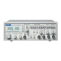
7
Installation
Mains Operating Voltage
The operating voltage of the instrument is shown on the rear panel. Should it be necessary to
change the operating voltage from 230V to 115V or vice-versa, proceed as follows:
1. Disconnect the instrument from all voltage sources.
2. Unclip the front bezel by gently pulling the centre of each long edge up and forward.
The case halves are held together by 4 plastic push-rivets. Use the blade of a small
screwdriver in the slot beside each rivet to first ease out the rivet head and then fully
remove the rivet body. Separate the case halves. Visit http://www.aimtti.com/support
for further details.
3. Remove the 6 screws securing the main pcb to the case upper and lift the pcb free,
complete with front and rear panels.
4. Change the appropriate zero-ohm links beside the transformer on the pcb:
Link LK2 only for 230V operation
Link LK1 and LK3 only for 115V operation
5. Refit the pcb to the case upper, ensuring all connections (especially safety earth) are
remade as before, and refit the case lower.
6. To comply with safety standard requirements the operating voltage marked on the rear
panel must be changed to clearly show the new voltage setting.
7. Change the fuse to suit the new operating voltage, see below.
Fuse
The correct time-lag fuse must be fitted for the selected operating voltage.
For 230V operation use 125mA (T) 250V HBC.
For 115V operation use 250mA (T) 250V HBC.
Make sure that only fuses with the required rated current and of the specified type are used for
replacement. The use of makeshift fuses and the short-circuiting of fuse holders are prohibited.
Mains Lead
When a three core mains lead with bare ends is provided it should be connected as follows:
Brown - Mains live
Blue - Mains Neutral
Green/Yellow - Earth
WARNING! THIS INSTRUMENT MUST BE EARTHED
Any interruption of the mains earth conductor inside or outside the instrument will make the
instrument dangerous. Intentional interruption is prohibited.
 Loading...