4
A1
A2
A1
A2
A1
A2
A1
A2
A1
A2
A1
A2
A1
A2
A1
A2
B1
B2
B1
B2
B1
B2
B1
B2
COMMON 1
SUB 1
SUB 2
A1
A2
A1
A2
~
COMMON 2
CN2
+
-
COMMON 1
R1
R2
R1
R2
~
COMMON 2
CN1
R1
R2
R1
R2
~
R1
R2
SUB 1A
R1
R2
R1
R2
~
SUB 1B
R1
R2
R1
R2
~
SUB 2A
R1
R2
R1
R2
~
SUB 2B
R1
R2
R1
R2
~
GTW-LC
USB
GT-VBX
GT-BCX
A1
A2
A1
A2
A1
A2
A1
A2
A1
A2
A1
A2
A1
A2
A1
A2
*DP
R1
R2
R1
R2
R1
R2
R1
R2
R1
R2
R1
R2
R1
R2
R1
R2
ON
123
4
ON
123
4
ON
123
4
ON
123
4
ON
123
4
ON
123
4
ON
123
4
ON
123
4
#1 #5#3 #7#2 #6#4 #8
R1
R2
R1
R2
+
-
IN
OUT
GT-MK
R1
R2
R1
R2
+
-
IN
OUT
GT-MK
+
-
PS24
ON
123
4
#2
ON
123
4
#1
+
-
PS24
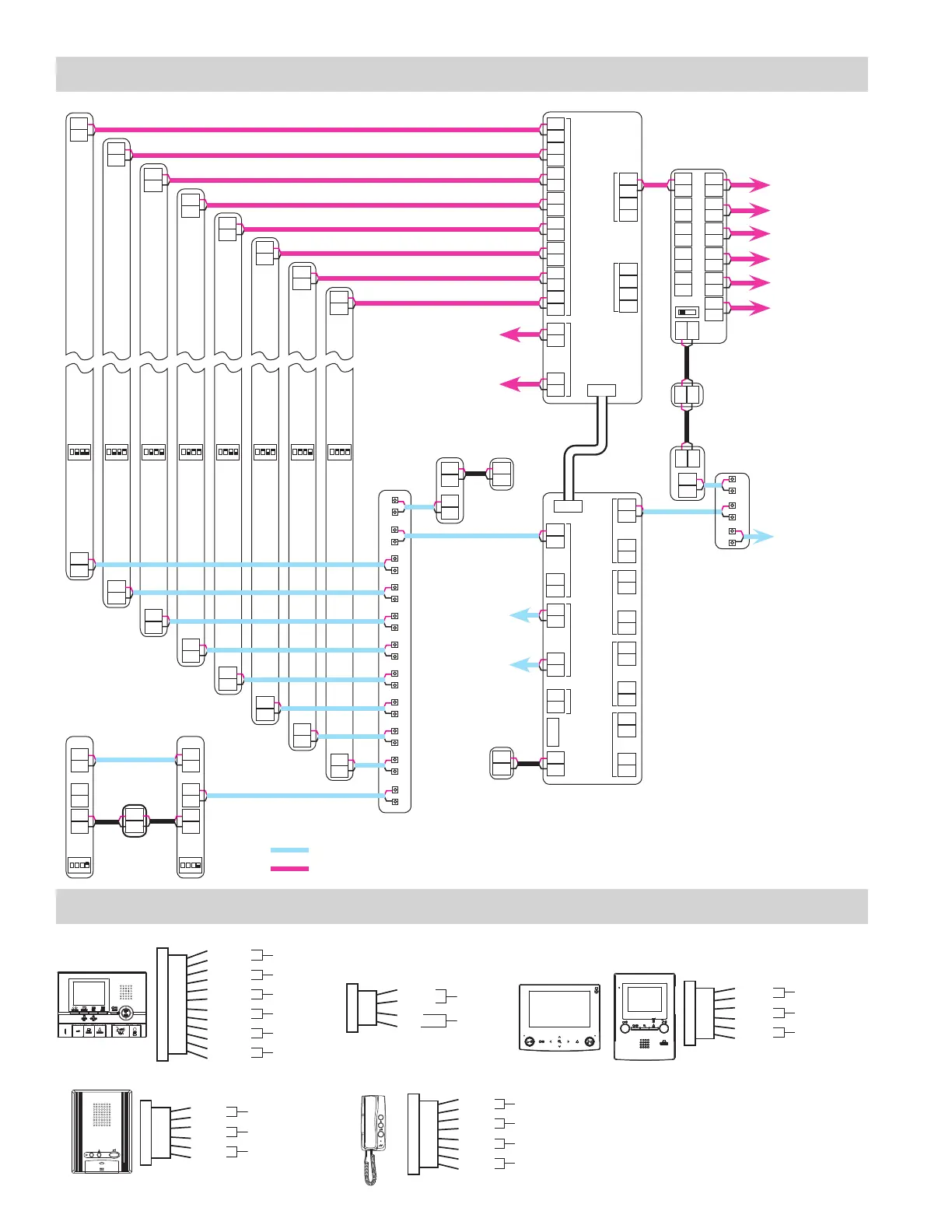
Connection
for video
entrance
modules 9-16
{
{
Connection
for audio
entrance
modules 9-16
R1
R2
+
-
GT-BC
+
-
PS24
+
-
A1
A2
A1
A2
A1
A2
A1
A2
A1
A2
B1
B2
B1
B2
B1
B2
B1
B2
B1
B2
B1
B2
+
-
EXP STD
+
-
R1
R2
*DP
PS24
GT-BC
Video outputs
to residential/
tenant stations
and / or GT-4Z
units. Max. of
25 residences
per trunk
and 125 total
residences per
GT-VBC.
Audio output
to residential/
tenant stations
and / or GT-4Z
units. Max. of
25 residences
per trunk
and 125 total
residences per
GT-BC.
GT-VAAGT-DA
SYSTEM WIRING: EXPANDED SYSTEM
OPTION CONNECTOR: RESIDENTIAL/TENANT STATIONS
GT-VBC
K
KE
RY
RY
SW
SW
S1
S1E
S2
S2E
S3
S3E
DC
DC
RYC
RYC
SW
SW
DC
DC
RY
RY
SW
SW
GT-2C-L
GT-2C
GT-1A
GT-1C7-L
GT-1C7
GT-1M3-L
GT-1M3
*Distribution Point:
NOT provided by Aiphone
except for Europe. This can
be any device that parallels
or commons the R1 / R2
connection. (Terminal strip,
punch down block, wire
nuts, etc.)
V+
V
-
GT-1D
KE
C
K
CE
RY
RY
SW
SW
12-pin option connector
(Brown)
(Red)
(Blue)
(White)
(Gray)
(Black)
(Orange)
(Black)
(Yellow)
(Black)
(Purple)
(Black)
Emergency alarm
Call transfer
Option contact output
Security/Utility input 1
Security/Utility input 2
Security/Utility input 3
4-pin option connector
(not included)
Option connector
(Brown)
(Red)
(Orange)
(Yellow)
Video out
Display transfer
(Yellow)
(Orange)
(Blue)
(White)
(Gray)
(Black)
Doctor call (Automatic entry)
Call transfer
Option contact output
Option connector
(Yellow)
(Orange)
(Blue)
(White)
(Gray)
(Black)
Doctor call (Automatic entry)
Call transfer
Option contact output
Option connector
(Brown)
(Red)
(Orange)
(Yellow)
(Blue)
(White)
(Gray)
(Black)
Emergency alarm (JP1 is cut during use.)
Doorbell
Call transfer
Option contact output
: Audio line
: Video line
 Loading...