How to Install
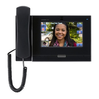
The illustrations explain installation using the IX-MV7-HW model.
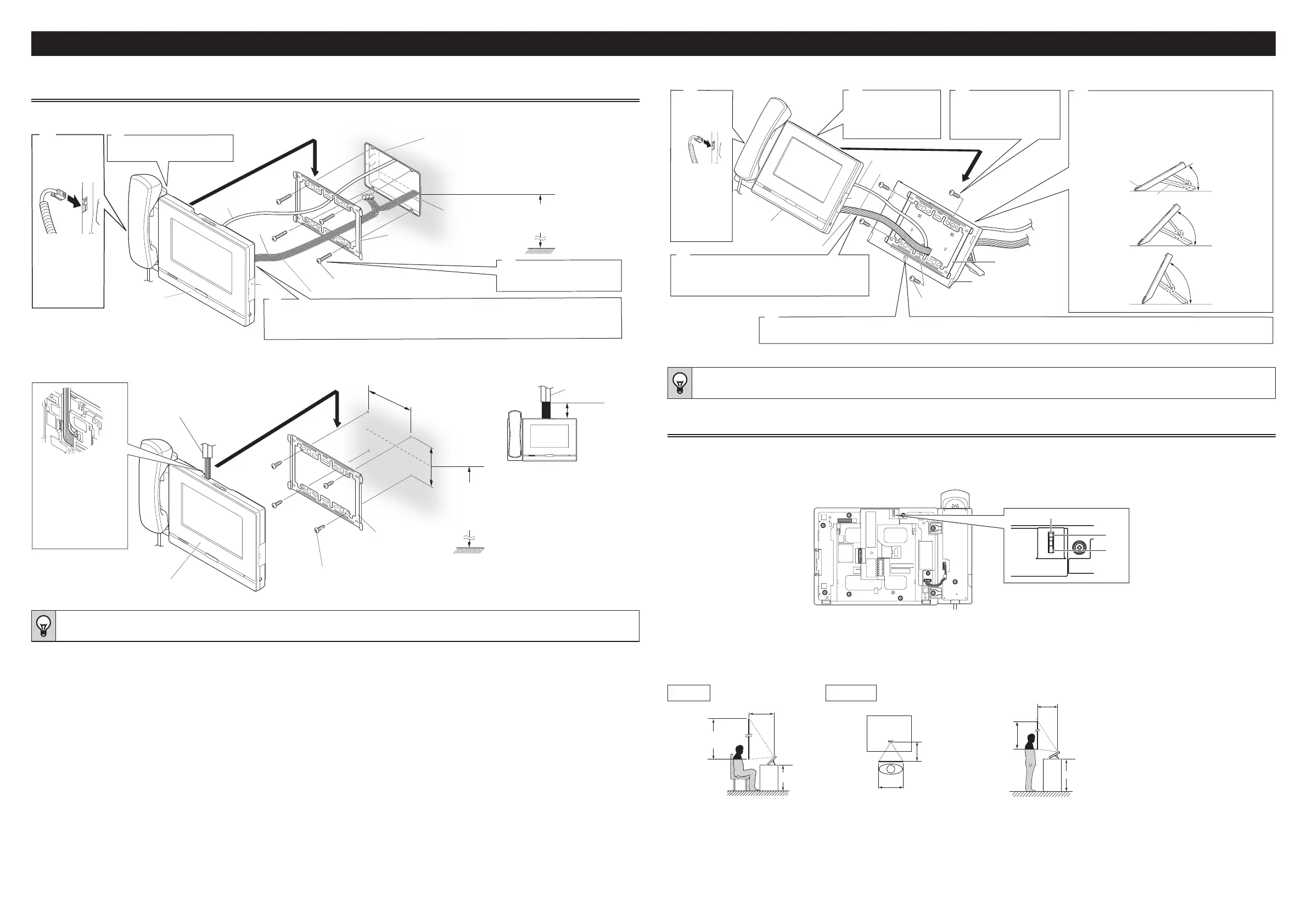
Installation of Master Station
■ Back wiring
2
1
Unit
Cat-5e/6 cable
Attach the unit to the
mounting bracket.
3-gang box
Mounting bracket
(attached to the back of the unit)
Low-voltage
lines
Mounting-bracket screws (included) × 4
Attach the mounting
bracket.
Connect the option connector (included) and the low-voltage lines
using crimping method, then connect the option connector, the
low-voltage lines and Cat-5e/6 cable.
Mounting height
(center of
gang
box)
1,500mm (4' 11'')
Low-voltage lines
Option connector (included)
Attach the
handset.
①
Insert the
connector into
the station unit
until it clicks.
②
Set the handset
on the unit.
*
* Insert a microSD card into the
microSD card slot if needed.
■ Surface wiring
Unit
Connect the option
connector
(included), the
low-voltage lines,
and Cat-5e/6 cable
to the unit, and
position them as
shown.
80mm (3-1/8'')
or less
Use a covering duct for Cat-
5e/6 cable and low-voltage
lines, and leave a space
(exposed portion) of no more
than 80mm (3-1/8'') between
the unit and the covering duct.
Wire mold
83.5mm (3-5/16'')
92mm (3-5/8'')
Recommended
Mounting height (center
of mounting bracket)
1,500mm (4' 11'')
(max.1,850mm (6' 3/4"))
Mounting bracket
Wall-mounting wood screws
(included) x4
Wire mold
(Please prepare separately)
Please decide the size of the wire mold according
to the wiring cables to accommodate.
• If the accessory screws are unusable for plaster board or a concrete wall, etc., please use a product such as an anchor or concrete plug (not included).
■ Mounting on the desktop stand
5
3
30°
45°
60°
Connect the option connector
(included), low-voltage lines, and
Cat-5e/6 cable to the unit.
Assemble the desktop stand.
* Position the desktop stand on a flat surface for stability.
Fix the desktop stand in place, if necessary.
* The desktop stand can be adjusted to any of 3 angles.
Fit the support into the grooves on the stand to set it at
the desired angle.
Attach the mounting
bracket to the
desktop stand.
Attach the unit to
the mounting
bracket.
Cat-5e/6 cable
Mounting bracket
Desktop stand (included)
Option connector (included)
Desktop stand screws
(included) ×4
Fasten the unit and the desktop stand together with a desktop-stand fastening screw (included) from the back
of the desktop stand.(Viewed from the back, there is a desktop-stand fastening screw hole in the lower center.)
Unit
Support
Stand
Attach the
handset.
①
Insert the
connector into
the station
until it clicks.
②
Set the
handset on
the unit.
* Insert a microSD card into the microSD card slot if needed.
*
Low-voltage lines
• Fasten the mounting bracket to the desktop stand with the supplied screws.
• If necessary, secure the Cat-5e/6 cable or low-voltage line using the included cable tie.
• When using the Desktop mounting, use the included Desktop stand.
Camera View Range and Mounting Position
■ Camera View adjustment
Using the camera angle adjustment lever, the camera can be tilted down (0° to -20°). Please adjust the camera to the optimal position.
-20°
0°
(Back view)
Camera angle adjustment lever
■ Camera view range
The camera range as illustrated is only an approximate indication and may vary according to the environment.
When installed on a flat desktop (with desktop stand at 45° and camera
angle at the lowest position [-20°])
Vertical Horizontal
400mm
(1' 4'')
500mm (
1' 7'')
Height of
desk
1300mm
(4' 3'')
900mm
(2' 11'')
700mm (
2' 3'')
460mm (1' 6'')
500mm
(
1' 7'')
When installed on a flat desktop (with desktop stand at 30° and camera
angle at the lowest position [-20°])
600mm (
1' 12'')
1850mm (6' 1'')
1250mm (4' 1'')
Height of desk
500mm (
1' 7'')
950mm (3' 1'')
2
 Loading...