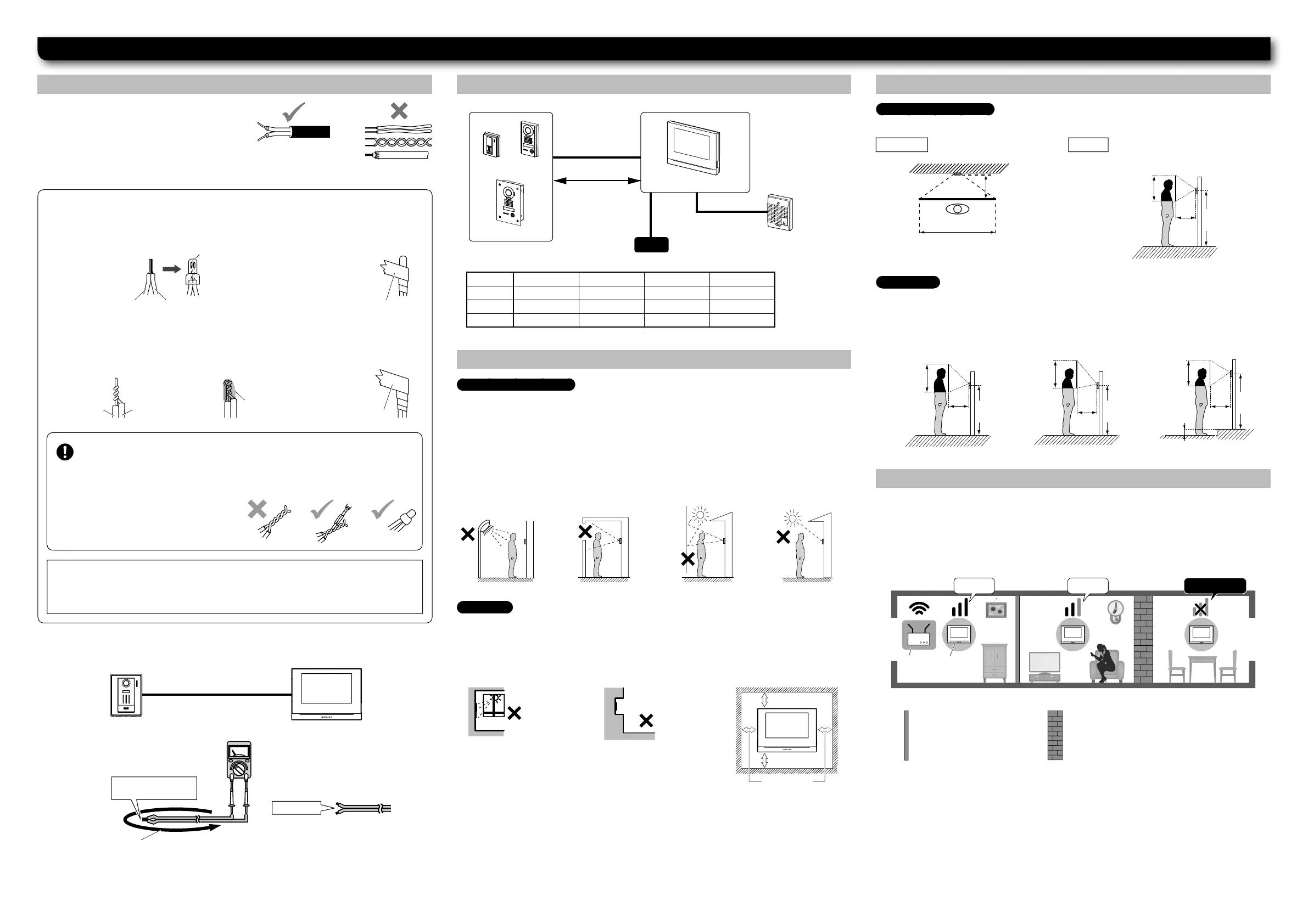
Installation
Cable Wiring method, wiring distance
Mounting locations
Mounting positions and image view area
Wi-Fi installation requirements
•
Use PE (polyethylene)-insulated PVC jacket
cable.
Parallel or jacketed 2-conductor,
mid-capacitance non-shielded cable is
recommended.
•
Never use individual conductors, twisted pair cable or coaxial cable.
JO-DA, JO-DV, JO-DVF
Do not install the door station in any of the following locations where lighting or the
ambient environment could impact the camera of the unit.
JO-1MDW
• When using existing cables
Check for short circuit and disconnection before installation.
•
Do not install the master
monitor station at a
location exposed to direct
sunlight.
•
Do not embed the master monitor station inside a wall.
•
The reset button is on the left side and the microSDHC card slot is on the right side of
the master monitor station. Be sure to install the station at a location where all buttons
can be reached by hand.
•
Install the master monitor station more than 3meters apart from all wireless equipment.
• Partition masonry walls
• Wood walls
• Plasterboard walls
• Reinforced concrete walls
• Load-bearing walls
• Stone walls
• Metal walls
•
Avoid installing the
master monitor station
in a concave space of
a wall to prevent audio
distortion.
•
Where the sky
fi lls much of the
background
•
Where the
background of the
subject is white.
•
Make sure to leave at
least the specifi ed spaces
on all sides to prevent
malfunction and audio
distortion.
Disconnection check (6Ω or less)
Connect the ends of one side and make a
measure at the other side with a tester.
Short circuit check:
∞
Ω (Infi nity)
To connect low voltage wires, either crimp them with a crimp sleeve or solder
them, and then insulate by covering with insulating tape.
[Crimping with a crimp sleeve]
[Soldering]
1. Line up solid and
stranded conductors,
and crimp them.
1. Twist the stranded
conductor around the
solid conductor at least
three times.
2. Bend the tip and solder it.
Make sure no lead wire
sticks out.
3. Overlap more than half of
the width and twist them at
least twice.
2. Overlap more than half
of the width and twist
them at least twice.
Keep the number of connections as low as possible when wiring.
After connecting wires, always check for breaking or insuffi cient connection.
Especially when connecting a wire in the middle of wiring, either crimp it with a
crimp sleeve or solder it, and then insulate it by covering with insulating tape.
Just twisting wires may cause poor connection,
or the surface of the wires may get oxidized
and cause a loose connection, leading to
malfunctioning or failure.
NOTES:
• If the lead wire with a connector is short, extend it by using an interconnecting cable.
• Connectors have polarity, so pay attention and connect properly. If connected incorrectly,
the device won’t work.
Ø 0.65 mm 22 AWG Ø 0.8-1.2 mm 20-16 AWG
A 50 m 165′ 100 m 330′
B5 m 16′ 10 m 33′
C 50 m 165′ 150 m 490′
JO-DA, JO-DV, JO-DVF
The master monitor station incorporates wireless LAN antennas. The Wi-Fi signal may not
reach the master monitor station depending on the installation environment such as wall
materials or the number of walls. Make sure the master monitor station receives a Wi-Fi
signal successfully before installing the master monitor station. If the Wi-Fi signal does
not reach the master station, change the installation location of the router or the master
station.
JO-DA only
: Refer to the diagrams below when the camera angle is changed with the
adjustment switch.
•
Where sunlight or
other strong light
sources will shine
directly into the
camera
•
Where lights will
be shining directly
into the camera
night time
No GoodGoodGood
 Loading...