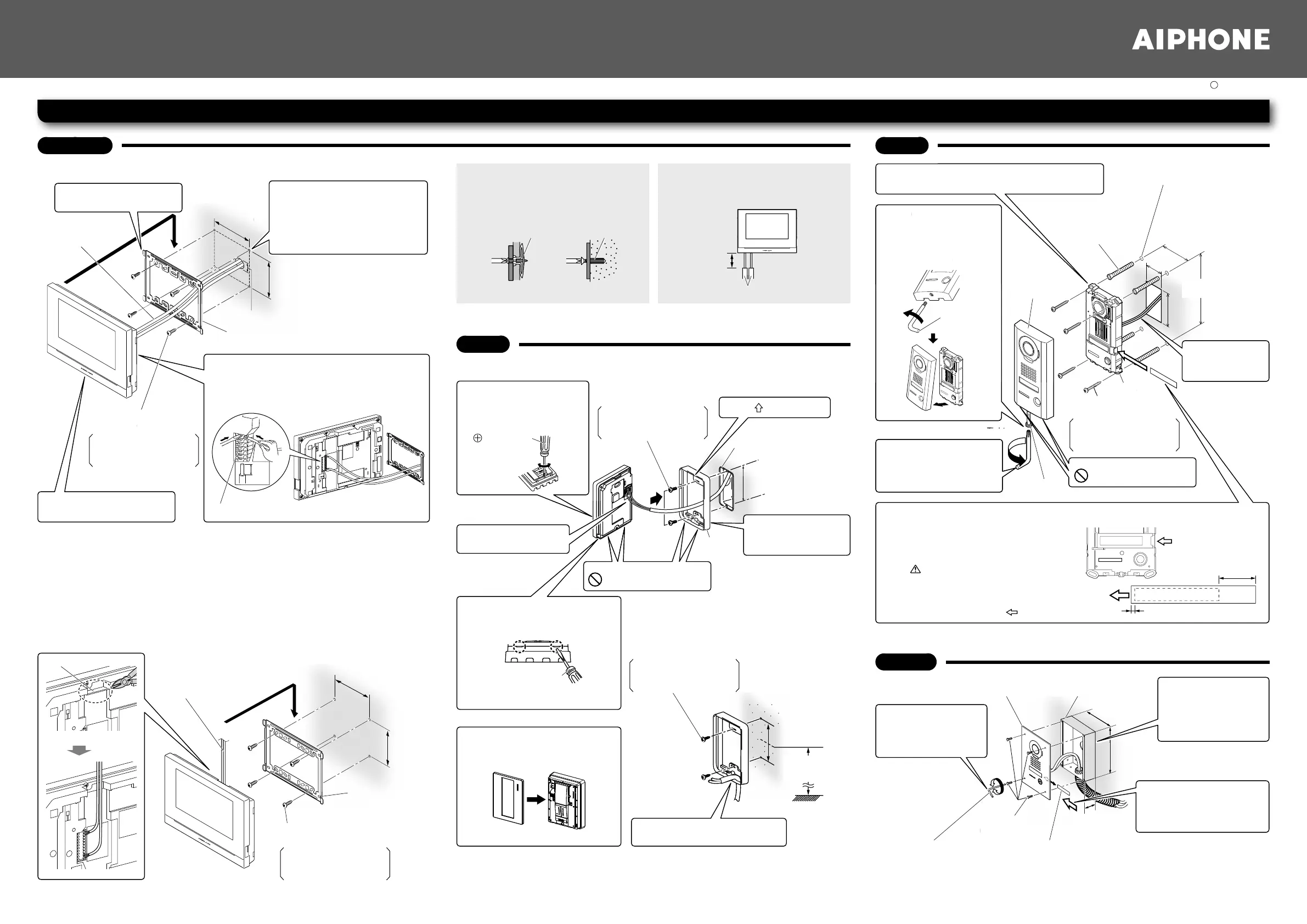
Mounting bracket
(attached to the station)
Ø 50 mm (1-15/16″)
83.5 mm
(3-5/16″)
8 mm
(3/8″)
92 mm
(3-5/8″)
(e.g.)
Board anchor Concrete plug
80 mm or less
Molding
Wood mounting screw × 4
(not included)
Release button
Wires
4
Mount the station on
the mounting bracket.
2
Fasten the mounting
bracket to the wall.
3
Connect wires.
1. Press the release button (to insert or remove
the wire).
2. Insert the wire into the terminal.
Screw shaft: Ø 4.1 or less
Slotted head: Ø 8.2 or less,
3.0 mm or less in height
Wires
Cable inlet
83.5 mm
(3-5/16″)
92 mm
(3-5/8″)
Mounting bracket
(attached to the
station)
Wood mounting screw × 4
(not included)
Screw shaft: Ø 4.1 or less
Slotted head: Ø 8.2 or less,
3.0 mm or less in height
2
Remove the main unit
from the mounting
frame by loosening
the locking screws
1
Loosen the special
screw with the
special screwdriver,
and remove the
front panel.
Screwdriver
Tighten Loosen
Tighten
Special screw
Vandal resistant
front panel
(The diameter and the
depth of the holes on the
wall depend on the anchors
suitable for the mounting
screws used.)
The unit
Place “ UP” upwards
Do not block the holes.
When wood mounting screws cannot be used
for plasterboard walls, concrete walls and so
on, use commercially-available board anchors
or concrete plugs.
Use cable molding for the power wire and
weak electric wires. A bare wire part between
the station and cable molding should be
80 mm or less.
Installation height
(center of the unit)
1,500 mm (5′)
1-gang box
Front panel Main unit
Mounting
frame
Drainage holes
83.5 mm
(3-5/16″)
4
Connect wires.
Insert a wire from the lower side.
3
Fasten the
mounting frame
to the wall.
Wire slot
<Bottom surface>
83.5 mm
(3-5/16″)
Flathead screwdriver
Pry off the front panel with a fl athead
screwdriver.
Mounting screw × 2
(not included)
Mounting screw × 2 (not included)
4
Fasten the unit to the mounting surface.
* Use board anchors or concrete plugs as needed.
5
Replace face plate
and tighten screw
with included
special screwdriver.
5
Mount the main unit on the
mounting frame, and fi t the
front panel on.
1
Remove the front panel from
the main unit.
1
Install the fl ush
mount back box
in the wall, and
then connect the
wires to the unit.
3
Fasten the front
panel to the back
box with the
special screws.
2
Insert the transparent
name plate.
* See the step 2 of JO-DV
above for details.
2
Insert the transparent name plate.
1. Peel off the protective seal of the plate
(both sides).
2. Fill in the name on the transparent name
plate.
Be sure to leave 25 mm (1″) of white
space on the right end to account for
insertion.
3. Insert the fi lled-in transparent name plate
as below (indicated with
in diagram).
3
Connect
wires to the
unit.
Do not block the holes.
Drainage holes
Special
screwdriver
(included)
Loosen
Anchor × 4 (not included)
(Prepare anchors
according to the size of
the mounting screws.)
Mounting screw × 4
(not included)
150 mm
(5-15/16″)
75 mm
(3″)
50 mm
(1-31/32″)
70 mm
(2-3/4″)
Insert transparent
name plate here.
25 mm (1″)
2 mm (1/8″)
180 mm
(7-3/32″)
45 mm
(1-25/32″)
Transparent name plate
Flush mount back
box (included)
Vandal resistant front panel
with the unit attached
Special screwdriver
(Hexagonal wrench) (included)
Special screw × 4
(included)
Loosen
Tighten
110 mm
(4-3/8″)
Screw shaft: Ø 4.1 or less
Slotted head: Ø 8.2 or less,
3.0 mm or less in height
Screw shaft: Ø 4.1 or less
Slotted head: Ø 8.2 or less,
3.0 mm or less in height
Screw shaft: Ø 4.1 or less
Slotted head: Ø 8.2 or less,
3.0 mm or less in height
1
Cut a small round hole
(Ø 50 mm (1-15/16″)) in the
wall for routing wires.
* Cut a hole at a position shifted
25 mm to the right from the
station center.
Mounting
<Back wiring>
<Back wiring>
<Surface wiring>
<Surface wiring>
The wires can be routed to the top or bottom of the station.
Cut the cable inlet to allow passage of the wiring into the station from the top or bottom of
the station.
If there is a large amount of wiring, strip away the jacket of the wire up to the cable inlet.
JO-1MDW
JO-DA
JO-DV
JO-DVF
NOTE:
When using a gang box, select a 3-gang box.
Installation Manual
JO-1MDW (Master monitor station)
JOS-1AW (A set including JO-1MDW, JO-DA and power supply)
JOS-1VW (A set including JO-1MDW, JO-DV and power supply)
JOS-1FW (A set including JO-1MDW, JO-DVF and power supply)
Issue date: Dec. 2018 FK2603 A P1218 HZ 61036
 Loading...