Do you have a question about the Air Lift Load CONTROLLER I 25655 and is the answer not in the manual?
Highlights critical safety information and vehicle load limits.
Explains the meaning of hazard notations and notes used in the guide.
Guidance on selecting a dry, protected area for compressor placement.
Instructions for selecting a location and securing the compressor unit.
Steps for positioning and securing the gauge panel onto the vehicle's dash.
Details on connecting the compressor, dash panel, and power source.
Steps for cutting, routing, and connecting air lines to springs and control panel.
Guide on adjusting air pressure for ride quality and operating the system.
Solutions for common problems like compressor not running or air leaks.
Provides phone numbers, mailing, and email addresses for customer support.
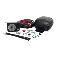
The Air Lift LoadController I Kit 25655 is a single gauge controller designed to assist with the installation, maintenance, and troubleshooting of an air spring system, specifically the LoadController I system. This kit is intended to be installed after the air spring kit has been set up.
The LoadController I system provides on-board air control for air springs, allowing the user to adjust air pressure to maintain a level vehicle and optimize ride and handling. It includes a compressor, a dash-mounted gauge panel, and the necessary air lines and electrical connections to integrate with an existing air spring setup. The system enables manual inflation and deflation of the air springs directly from the vehicle's cabin.
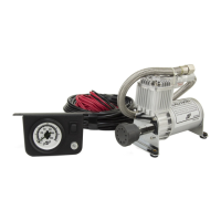
The compressor is responsible for generating the air pressure needed to inflate the air springs. It is designed to be mounted in a dry, protected area of the vehicle, shielded from direct splash, excessive moisture, and high heat environments. The compressor can be mounted in various orientations (vertical, upside down, sideways) as long as its intake filter is oriented to allow moisture to drain easily, especially if mounted outside the vehicle.
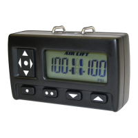
The dash panel features a single gauge that displays the current air pressure in the air springs. It also includes an ON/OFF switch to activate the compressor and a button to deflate the air springs. The gauge is illuminated for visibility.
The air line system connects the compressor to the air springs via a series of tees and fittings. This network ensures that air can be directed from the compressor to inflate the air springs and that pressure can be released when deflation is desired.
Inflation Control: The system allows for manual inflation of the air springs. By depressing the ON/OFF switch on the dash panel, the compressor automatically turns on and increases the air pressure in the air springs, as indicated on the gauge. Once the desired pressure is reached, releasing the switch will shut off the compressor.
Deflation Control: To deflate the air springs, the user simply depresses the button located below the ON/OFF switch on the dash panel. This releases air from the system, lowering the pressure in the air springs.
Ride and Handling Adjustment: The primary purpose of the LoadController I is to help level the vehicle and provide the best possible ride and handling. Users are guided to initially fill the air springs to their maximum recommended pressure. From there, they can decrease the pressure in five-pound increments to find the optimal setting for their particular vehicle, considering that the rear springs should be slightly arched if the vehicle is equipped with leaf springs. Adjustments can be made to compensate for additional loads, trailers, or changes in weight distribution.
Duty Cycle Management: It is crucial to adhere to the recommended duty cycle for the compressor, which is 15% (3 minutes on and 20 minutes off). Exceeding this duty cycle can lead to premature failure of the compressor.
Safety Considerations: The system does not alter the Gross Vehicle Weight Rating (GVWR) or payload of the vehicle. Users must always refer to their vehicle's owner's manual and not exceed the maximum load specified by the manufacturer.
Leak Detection: Regularly checking the inflation pressure is an important maintenance step. Air spring bellows naturally permeate (lose pressure through the rubber wall) at an approximate rate of 3-4 p.s.i. per week. A higher rate of pressure loss indicates a leak. To find a possible leak, the system should be inflated to the maximum recommended pressure, and all fittings should be sprayed with a soapy water solution. Leaks will be indicated by bubbles. Specific areas to check include the inflation valve (including the valve core and air line connections) and the elbow fitting where it threads into the bellows (ensuring pipe sealant is applied) and its air line connection. If a leak is found, the air pressure should be reduced to zero, and threaded connections should be tightened, or the air line should be removed, cut by one inch, and reattached.
Compressor Overheat Protection: In the event that the compressor stops running, it may be due to overheating. The user should allow the compressor to cool down and provide adequate time for the thermal breaker to reset before attempting to restart it.
Air Line Management: During installation, it is emphasized to keep air lines away from heat sources (such as the exhaust system) and moving chassis components. Securing the air lines to the frame with nylon tie straps is recommended to prevent damage and ensure longevity.
Component Replacement: If any parts are missing, damaged, or defective, or if technical assistance is needed, users are advised to contact Air Lift customer service. Most parts are readily available for replacement.
| Part Number | 25655 |
|---|---|
| Input Voltage | 12V DC |
| Product Name | Air Lift Load CONTROLLER I |
| Type | Controller |
| Application | Air Suspension Systems |
| Features | easy installation |
| Compatibility | Compatible with Air Lift air spring systems |