Load Controller / Single
Installing the Load Controller
ag
e System
GETTING STARTED
This part of the installation should be done after the air spring kit is installed. If you
have any questions, please call Air Lift customer service at (800) 248-0892.
If you are adding this control system to an Air Lift LoadLifter5000 application, then no
modifications to the low pressure sensor are necessary. If you are adding this control system
to an Air Lift 1000 or RideControl application, and if your specific application requires a
minimum of 10 p.s.i., then it will be necessary to adjust the low pressure sensor to 10 p.s.i.
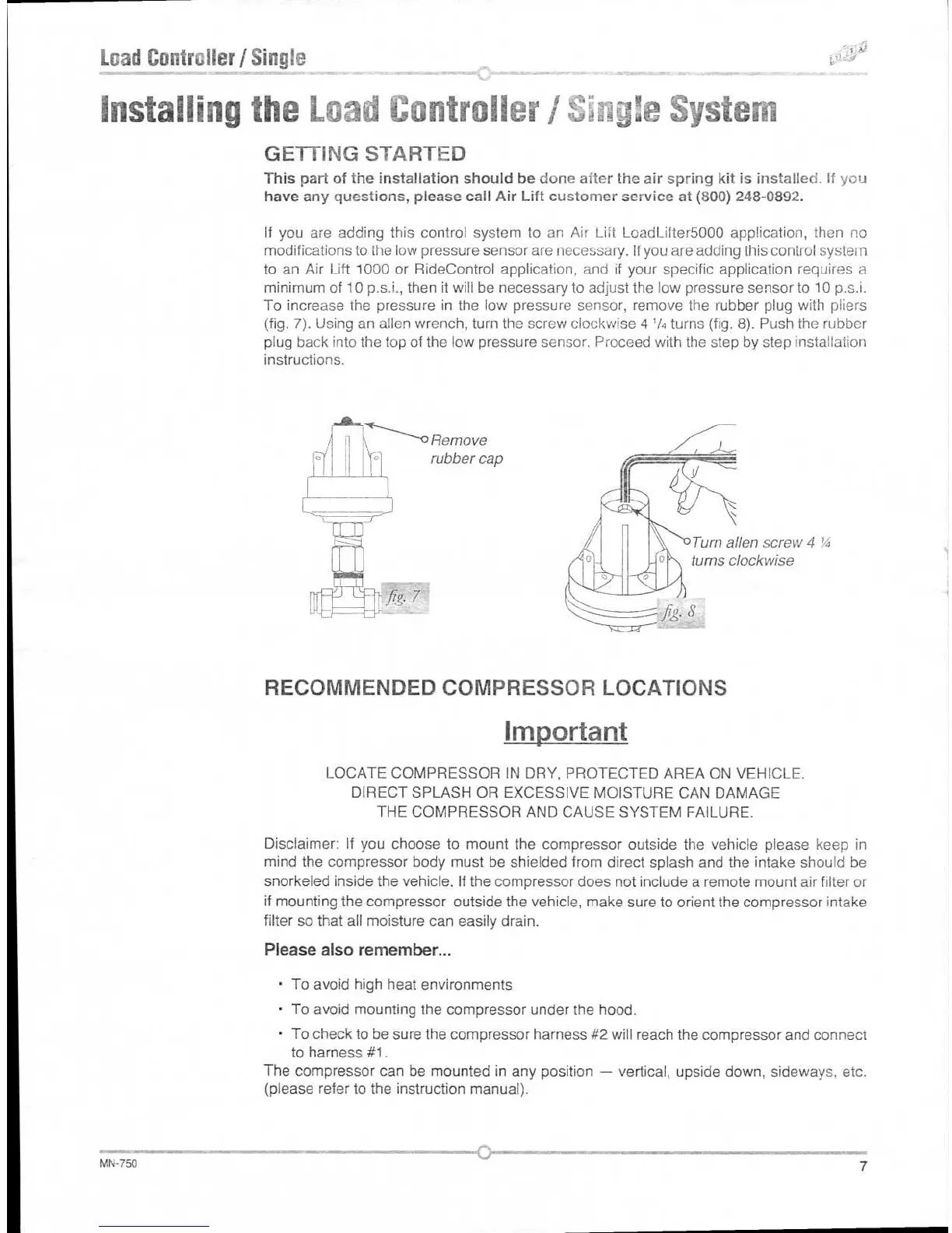
To increase the pressure in
the low pressure sensor,
remove the rubber plug with pliers
(fig. 7). Using an alien wrench, turn the screw clockwise 4
1
/4 turns (fig. 8). Push the rubber
plug back into the top of the low pressure sensor. Proceed with the step by step installation
instructions.
Turn alien screw 4 'A
turns clockwise
RECOMMENDED COMPRESSOR LOCATIONS
Important
LOCATE COMPRESSOR IN DRY, PROTECTED AREA ON VEHICLE.
DIRECT SPLASH OR EXCESSIVE MOISTURE CAN DAMAGE
THE COMPRESSOR AND CAUSE SYSTEM FAILURE.
Disclaimer: If you choose to mount the compressor outside the vehicle please keep in
mind the compressor body must be shielded from direct splash and the intake should be
snorkeled inside the vehicle. If the compressor does not include a remote mount air filter or
if mounting the compressor outside the vehicle, make sure to orient the compressor intake
filter so that all moisture can easily drain.
Please also remember...
•
To avoid high heat environments
•
To avoid mounting the compressor under the hood.
•
To check to be sure the compressor harness #2 will reach the compressor and connect
to harness #1.
The compressor can be mounted in any position — vertical, upside down, sideways, etc.
(please refer to the instruction manual).
MN-750
7
Remove
rubber cap
 Loading...