9
STEP 7)
Hold the “ON/OFF/TEST” switch in the “TEST” position. All local and remote au-
dible/visual indicators will activate. If indicators do not activate, check all electri-
cal connections, then call factory repair dept.
Note: An alarm funcon test can be performed at any me by liing the “ON/OFF/
TEST” switch to the “TEST” posion.
STEP 9)
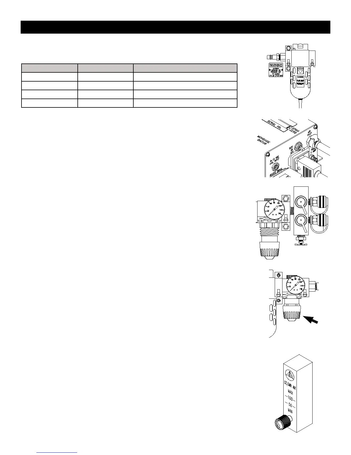
Adjust the outlet pressure to the setting recommended by the respirator manufacturer.
Turn the knob clockwise to increase pressure, counterclockwise to decrease pressure.
STEP 10)
Adjust CO monitor air sample ow rate by turning the owmeter control knob counterclockwise
until the ball hovers between 50 and 100 cc/min. The box is now ready for operation.
The monitor will analyze the air sample and display the CO concentration in parts per million
(ppm). The system’s green “NORMAL” operation light will illuminate, and the red “HIGH CO”
light will icker faintly approximately every second when the CO level is below 10ppm (5ppm
Canadian).
When the CO concentration level exceeds the alarm set point, the green “NORMAL” light will
turn off, the red “HIGH CO” light illuminates, the audible alarm will sound, and the remote alarm
connections will energize.
When CO concentrations drop below the alarm set point, all alarm indicators will deactivate and
return to normal operation.
MODEL # MIN. HOSE I.D. INLET FITING
BB15 SERIES 3/8” 1/2” INDUSTRIAL INTERCHANGE
BB30-100 SERIES 1/2” 1/2” INDUSTRIAL INTERCHANGE
BB150 SERIES 3/4” 1” FPT
BB250 SERIES 1” 1” FPT
STEP 6)
Connect the air source, 150 psi max., to the inlet tting.
STEP 8)
Attach desired respirators and hoses to the quick connect couplings.
Note: Some models may not have respirator connecons. They may be ordered with NPT out-
lets for connecon to points-of-aachment.
Setup And Operaon