Customer : CSN
Type : A318/A319/A320/A321
Rev. Date : May 01, 2018
Manual : AMM
Selected applicability : 0054-0054
29-32-12 PB 401 CONF 00 - PRESSURE
SWITCH - SYSTEM - REMOVAL/INSTALLATION
Print Date: July 05, 2018 Page 4 of 19
© AIRBUS S.A.S. ALL RIGHTS RESERVED. CONFIDENTIAL AND PROPRIETARY DOCUMENT.
(5) Loosen the system pressure switch (2) and remove it together with the O-ring (3) from the manifold
(4).
(6) Discard the O-ring.
(7) Install a PLUG - BLANKING in the open ports.
TASK 29-32-12-400-001-A
Installation of the System Pressure Switch
WARNING: MAKE SURE THAT THE TRAVEL RANGES OF THE FLIGHT CONTROL SURFACES ARE
CLEAR BEFORE YOU PRESSURIZE/DEPRESSURIZE A HYDRAULIC SYSTEM.
WARNING: MAKE SURE THAT THE GROUND SAFETY-LOCKS ARE IN POSITION ON THE LANDING
GEAR. THIS WILL PREVENT UNWANTED MOVEMENT OF THE LANDING GEAR, AND THUS
POSSIBLE INJURY TO PERSONS AND DAMAGE TO THE AIRCRAFT AND/OR EQUIPMENT.
FIN : 1151GN
1. Reason for the Job
Self explanatory
2 Job Set-up Information
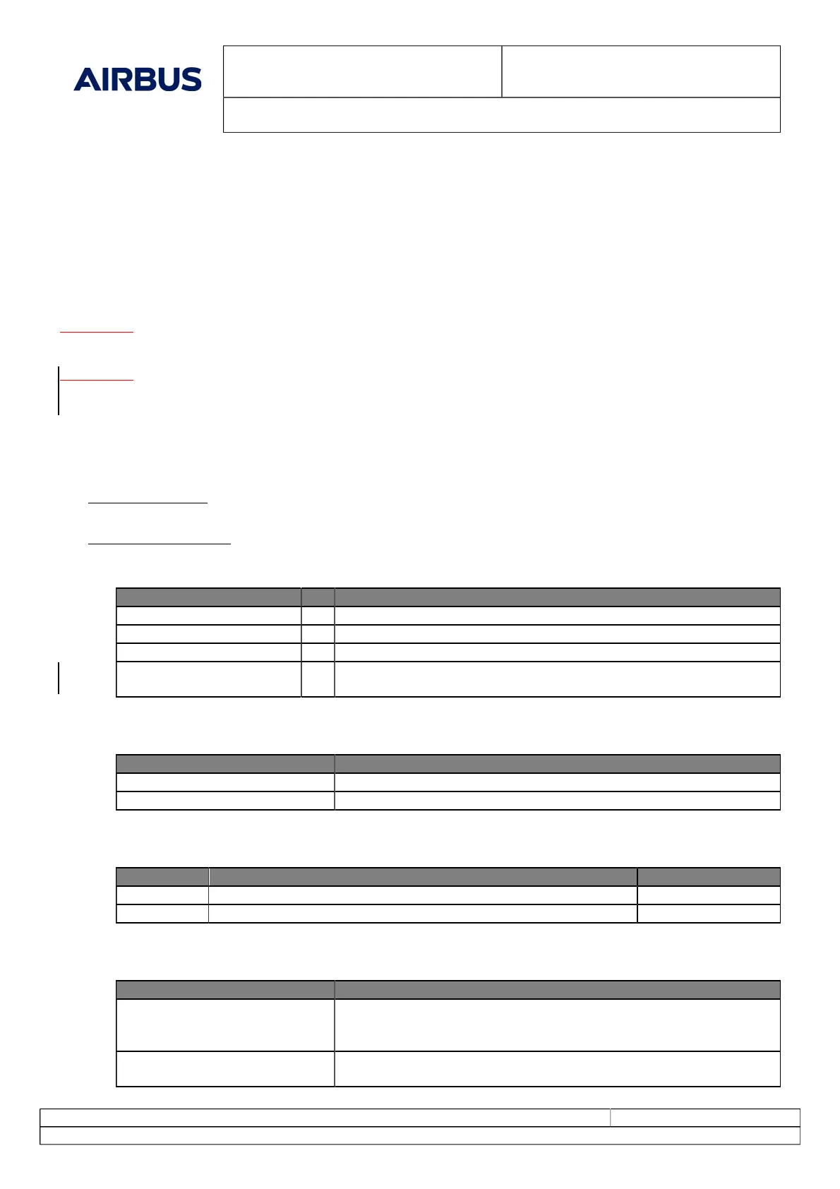
A. Fixtures, Tools, Test and Support Equipment
REFERENCE QTY DESIGNATION
No specific 1 ACCESS PLATFORM 3M (10 FT)- ADJUSTABLE
No specific 1 CONTAINER - HYDRAULIC FLUID RESISTANT
No specific 2 WARNING NOTICE(S)
No specific Torque wrench: range to between 3.20 and 3.45 m.daN
(23.60 and 25.44 lbf.ft)
B. Consumable Materials
REFERENCE DESIGNATION
(Material No. 02ABA1) Phosphate Ester Hydraulic Fluid-General Power - -
No specific lockwire, corrosion-resistant steel 0.8 mm (0.032 in.)
C. Expendable Parts
FIG.ITEM DESIGNATION IPC-CSN
3 O-ring 29-32-03-01-070
3 O-ring 29-32-83-01-090
D. Referenced Information
REFERENCE DESIGNATION
(Ref. 20-28-00-912-004-A). Electrical Bonding of Components With Conductive Bolts and Screws
and Bonding Straps in the Fuselage and in the Wings (this does not in-
clude the tanks)
(Ref. 29-00-00-864-001-A). Put the Related Hydraulic System in the Depressurized Configuration
before Maintenance Action
 Loading...