Angle Die Grinder
Model # 6255 /Composite
3 501A-003
1 25 222F-025 Motor Housing 1
2014.09
Tools of this class operate on a wide range of air pressure. It is recommended that air
pressure of these tools measures 90 PSI at the tool while running free. Higher pressure
and unclean air will shorten the tool’s life because of faster wear and may create a
hazardous condition and void the warranty.
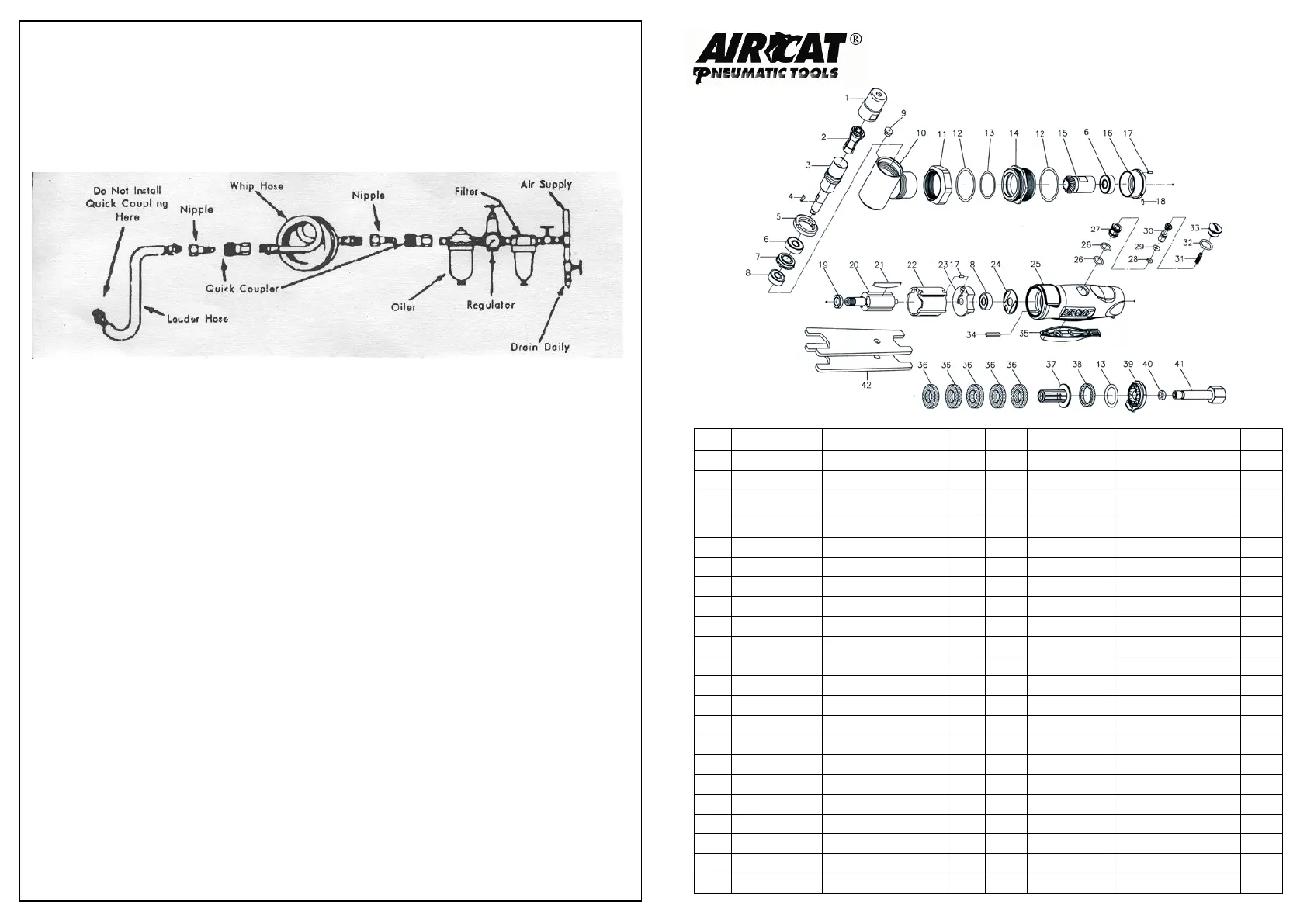
Water in the air line will cause damage to the tool. Drain the air tank daily. Clean the
air inlet filter screen on at least a weekly schedule. The recommended hookup
procedure can be viewed in the illustration below.
The air inlet, used for connecting air supply, has standard 1/4” NPT American Thread.
Line pressure should be increased to compensate for unusually long air hoses (over 25
feet). Minimum hose diameter should be 3/8”I.D. and fittings should have the same
inside dimensions.
Operating Instructions
1. Read safety instructions first.
2. The tool is started by depressing the throttle, which is spring loaded and when
released returns to off position.
3. Always wear protective safety goggles and clothing when operating tool.
4. DO NOT, UNDER ANY CIRCUMSTANCES, REMOVE THE DISC GUARD.
5. Use both hands when operating this tool.
6. Refer to safety instructions when operating this tool.
Maintenance
Other factors outside the tool may cause loss of power or erratic action. Reduced
compressor output, excessive drain on the air line, moisture or restriction in air pipes
or the use of hose connections of improper size or poor condition may reduce air
supply. Grit or gum deposits in the tool may cut power and may be corrected by
cleaning the air strainer and flushing out the tool with gum solvent oil or an equal
mixture of SAE#10 oil and kerosene. If outside conditions are in order and tool is
out-of-warranty, disconnect tool from hose, disassemble tool, replace worm or
damaged parts, clean, reassemble, and re-lubricate, or take tool to any air tool
service center. For tools in warranty period, send tool direct to Warranty Center. You
must send in your warranty card for warranty service.

 Loading...