Do you have a question about the AIREDALE Artus ARC66-21PE1H-7 and is the answer not in the manual?
Details Airedale's warranty, commissioning, and maintenance services for their products.
Information on obtaining spare parts for Artus units.
Details on Airedale's refrigeration and air conditioning training courses.
Guidelines for safe operation and maintenance of the Artus unit, emphasizing electrical safety.
Airedale's recommendation for using PPE during installation, maintenance, and commissioning.
Guidance on safe manual handling during unit servicing and maintenance.
Airedale's policy for addressing environmental issues and ensuring compliance with regulations.
Details Airedale's certification that equipment conforms to relevant EC Directives.
Specifies the operational temperature and pressure limits for the Artus unit.
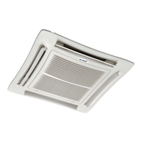
Overview of the Artus Low energy fan coil unit and its key features.
Focuses on the ease and speed of installation due to integrated components.
Describes the design features that facilitate easy and quick maintenance access.
Details the construction materials and design of the Artus chassis.
Describes the fascia material, colour options, and patterns for ceiling and exposed units.
Lists the available sizes for the Artus fascia plates for different ceiling systems.
Describes the fan and motor assembly, including shroud design and maintenance access.
Specifies the nominal airflow rate and specific fan power of the Artus unit.
Details the filter media, aperture size, and maintenance of the air filtration system.
Connection for the 230V/1PH/50Hz mains power supply.
Optional connection point for BACnet MS/TP communication.
Connection for a KNX display to a room sensor.
Connection for return air or optional room sensor/commissioning plug.
Connection for the main power supply to the fan.
The unit's main ON/OFF power switch.
Indicator LED for unit alarms.
Details the water coil construction, design variations, and heat transfer optimization.
Describes the single coil unit with an integrated PIC valve for single mode operation.
Details the unit with segregated cooling/heating coils and PIC valves for independent control.
Explains the combined coil system with a 3-port valve for switching between heating and cooling.
Diagram showing pipework connections for 2-pipe, 2-port PIC valve in cooling mode.
Diagram showing pipework connections for 2-pipe, 2-port PIC valve in heating mode.
Diagram illustrating pipework for 4-pipe, 2-coil segregated cooling and heating.
Diagrams for cooling and heating modes of a 4-pipe, 1-coil changeover unit.
Explains the function and characteristics of the 2-port PIC valve.
Describes the 3-port thermic valve used for changeover systems.
Details the condensate drain tray's function and removability for maintenance.
Highlights the condensate pump filter's removability for maintenance purposes.
Overview of the Artus controller, its BACnet compatibility, and integration capabilities.
Integrated controller for autonomous demand control using valves and EC fan.
Web server interface for unit setup, commissioning, and balancing.
Artus controls return air, fan speed, and valve operation for demand satisfaction.
Artus controls return air, fan speed, and valve operation for demand satisfaction.
Illumination of LEDs for alarm conditions like temperature discrepancy or condensate high level.
Details the features and operation of the optional Room Operator Unit.
Flow chart guiding the selection of unit coil type and supply airflow for cooling.
Procedure for selecting the low flow coil based on cooling conditions.
Procedure for selecting the high flow coil based on cooling conditions.
Flow chart for selecting unit coil type and supply airflow based on heating effect.
Procedure for selecting the low flow coil based on heating conditions.
Procedure for selecting the high flow coil based on heating conditions.
Graph for determining cooling effect based on supply airflow and water temps.
Graph for determining cooling effect with low flow coil based on airflow and water temps.
Graph for determining heating effect based on supply airflow and water temps.
Graph for determining heating effect with low flow coil based on airflow and water temps.
Graph for cooling effect of high flow segregated coils based on airflow and water temps.
Graph for cooling effect of low flow segregated coils based on airflow and water temps.
Graph for heating effect of segregated coils based on airflow and water temps.
Graph showing pressure drop for high flow coil changeover vs. water flow rate.
Graph showing pressure drop for low flow coil changeover vs. water flow rate.
Graph showing pressure drop for high flow segregated coils vs. water flow rate.
Graph showing pressure drop for low flow segregated coils vs. water flow rate.
Graph illustrating the relationship between supply airflow and overall sound power.
Octave band sound power levels for 1 coil units at various airflows and frequencies.
Octave band sound power levels for 2 coil units at various airflows and frequencies.
Estimates for acoustic performance without a consultant, for various case study scenarios.
Acoustic data and noise ratings for commercial offices with false ceilings.
Specifies maximum acoustic criteria for open plan and cellular offices.
Acoustic data and noise ratings for commercial offices with exposed services.
Acoustic data and noise ratings for residential and hotel living rooms and bedrooms.
Specifies acoustic criteria for residential projects in London.
Diagram and data showing air throw patterns and velocities for 140l/s airflow.
Graph showing absorbed fan power versus supply airflow for 1 and 2 coil units.
Graph showing specific fan power versus supply airflow for 1 and 2 coil units.
Details the operating limits for cooling, heating, water flow, and airflow of the Artus unit.
Provides cooling performance data for high water flow rate coils at various conditions.
Provides heating performance data for high water flow rate coils at various conditions.
Provides cooling performance data for low water flow rate coils at various conditions.
Provides heating performance data for low water flow rate coils at various conditions.
Summary of mechanical and electrical specifications including capacity, weight, and ratings.
Instructions for safely unpacking the Artus unit and checking its contents.
Instructions for safely unpacking the Artus decorative ceiling raft.
Diagrams showing pipework termination points for different Artus configurations.
Detailed dimensions of the Artus ceiling unit, including hanging centres.
Specifies required clearances and airflow paths for ceiling mounted units.
Details clearance requirements and raft opening for exposed unit installations.
Information on adjustable frames for precise unit positioning in ceiling voids.
Illustrates how the Artus unit integrates with different ceiling types (T-Bar, Plasterboard).
Procedure for mounting the ceiling raft to the unit's installation frame.
Steps for levelling the raft mounting frame and attaching the decorative raft.
Instructions for connecting the condensate drain and ensuring proper fall.
Procedure for bleeding air from the coil, including access and precautions.
Details electrical connections for mains, sensors, and BACnet/KNX communication.
Wiring diagram for MS/TP BACnet connections.
Wiring diagrams for BACnet/IP Ethernet connections.
Comprehensive wiring diagram for the Artus unit, showing all connections and components.
Details the unit's waterside connections and pipework termination types.
Guidance on chilled water pipework installation, water treatment, and glycol use.
Diagram for a valid 2-pipe Artus installation, with notes on 4-pipe systems.
Simplified diagram for 2-pipe cooling-only pipework installation.
Simplified diagram for 2-pipe heating-only pipework installation.
Simplified diagram for 4-pipe cooling/heating changeover pipework installation.
Illustrates the components and connections of the optional commissioning valve set.
Lists the main components, materials used, disposal method, and weight.
Explains the factory settings and procedure for commissioning the PICV.
Details flow adjustment for the PICV by setting the preset position dial.
Instructions on how to adjust the PICV flow rate by rotating the dial.
Describes the use of valve override plugs for simulating heating/cooling demands.
Step-by-step guide for commissioning thermic valves using override plugs.
Highlights how the unit design facilitates easy servicing and part replacement.
Safety precautions for electrical work during maintenance, including isolation.
General maintenance advice, including isolating power and following the schedule.
Maintenance schedule for filters (3, 6, 12 month checks).
Maintenance schedule for fan impeller (6 month check).
Details checks for filters, including cleaning, replacement, and disposal.
Details checks for fan impeller, water control valves, and condensate systems.
Details checks for controls, chassis, coils, and filter replacement.
Step-by-step guide for opening the Artus unit to access internal components.
Illustrated procedure for changing the Artus unit filters.
Procedure for removing and cleaning the condensate drain tray.
Instructions for removing the Artus fascia using self-tapping screws.
Guide for removing oversized fascia, including care for spacers.
Lists common faults, their possible causes, and remedies for unit operation.
Troubleshooting steps for when the unit is not providing cooling.
Troubleshooting steps for when the unit is not providing heating.
Details fault conditions indicated by control panel LEDs and their statuses.
Explains the condensate pump LED status indicators and associated faults.
Details Airedale's product warranty terms, coverage, and validity conditions.
Steps for obtaining replacement parts under warranty and returning faulty components.
Reasons why warranty may be refused, such as misapplication or incorrect installation.
| Model | ARC66-21PE1H-7 |
|---|---|
| Category | Air Conditioner |
| Cooling Capacity | 6.6 kW |
| Heating Capacity | 7.0 kW |
| Energy Efficiency Ratio (EER) | 3.21 |
| Coefficient of Performance (COP) | 3.61 |
| Refrigerant | R410A |
| Sound Pressure Level (Indoor) | 42 dB(A) |
| Sound Pressure Level (Outdoor) | 52 dB(A) |
| Net Weight (Indoor) | 12 kg |
| Power Supply | 230V, 50Hz |