Do you have a question about the AIREDALE Artus ARC66-42PE1L-7 and is the answer not in the manual?
Covers warranty, commissioning, and maintenance services provided by Airedale.
Information regarding the availability of spare parts for the Artus unit.
Details on training courses offered by Airedale for HVAC.
Information on safety standards and precautions for operating the equipment.
Recommendations for using PPE and guidance on manual handling.
Airedale's environmental policy and lists EC Directives compliance.
Specifies operational limits and declares ROHS compliance.
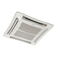
Overview of the Artus unit and its key features.
Highlights ease of installation and hassle-free maintenance access.
Details clean aesthetics and quiet operation capabilities.
Explains the model naming convention with examples.
Details chassis construction and removable fascia.
Provides fascia dimensions and exposed unit raft details.
Describes fan assembly, materials, and maintenance access.
States airflow rate, fan power, and filtration details.
Specifies mains power and optional BACnet MS/TP connections.
Details connections for KNX and BACnet IP communication.
Identifies control valves, temperature sensors, and ports.
Locates fan connections, power switch, and fuses.
Describes fascia interlock, alarm LED, and power indicators.
Details high flow and low flow coil designs and applications.
Explains 2-pipe, 4-pipe segregated, and 4-pipe changeover systems.
Illustrates pipework connections for 2-pipe cooling and heating modes.
Shows pipework for segregated cooling and heating coils.
Illustrates pipework for 4-pipe changeover systems (cooling/heating).
Explains the function and operation of the 0-10V PIC valve.
Describes the 3 port valve used in changeover systems.
Details the features and specifications of the condensate pump.
Describes the condensate drain tray and its filter.
Introduces the Artus controller and its USB port.
Details sensor connections and BACnet/KNX ports.
Identifies fan speed, valve control, and alarm outputs.
Explains the integrated control system and its key features.
Describes unit operation, temperature control, and alarm indications.
Explains energy efficiency indicator and optional room sensor.
Specifies the location for the return air temperature sensor.
Flowchart for selecting unit coil type and airflow for cooling.
Flowchart for selecting unit coil type and airflow for heating.
Graph showing cooling capacity vs. airflow for high flow coils.
Graph showing cooling capacity vs. airflow for low flow coils.
Graph showing heating capacity vs. airflow for high flow coils.
Graph showing heating capacity vs. airflow for low flow coils.
Graph for cooling effect with high flow segregated coils.
Graph for cooling effect with low flow segregated coils.
Graph showing heating effect for segregated coils.
Graphs showing pressure drop vs. water flow rate for coils.
Graphs for pressure drop vs. water flow in segregated coils.
Graph showing sound power levels based on supply airflow.
Provides estimations for projects without a consultant.
Noise rating data for commercial offices with false ceilings.
Noise rating data for offices with exposed services.
Noise rating data for residential and hotel living rooms/bedrooms.
Graph showing absorbed fan power vs. supply airflow.
Graph showing specific fan power vs. supply airflow.
Details the operational and storage limits of the Artus unit.
Provides cooling performance data for high flow coils.
Provides heating performance data for high flow coils.
Provides cooling performance data for low flow coils.
Provides heating performance data for low flow coils.
Summarizes mechanical and electrical specifications and ratings.
Step-by-step guide for unpacking the Artus unit and checking parts.
Instructions for unpacking the Artus decorative ceiling raft.
Diagrams showing pipework connection points for different configurations.
Provides dimensional drawings and measurements for the ceiling unit.
Specifies required clearances and airflow paths for ceiling installations.
Details clearance and airflow needs for exposed unit installations.
Information on adjustable frames for unit mounting.
Illustrates different ceiling integration methods and dimensions.
Procedure for mounting the raft bracket and securing the raft.
Continues the procedure for leveling and attaching the decorative raft.
Explains the condensate removal process and connection requirements.
Instructions for bleeding coil air and locating sensors.
Details wiring for unit communication and optional room sensors.
Wiring diagrams for BACnet MS/TP and Ethernet connections.
Provides a detailed wiring diagram for the Artus unit.
Details water connection fittings and system installation guidelines.
Shows valid pipework installations for 2-pipe systems.
Simplified diagram for 2-pipe cooling only pipework.
Simplified diagram for 2-pipe heating only pipework.
Simplified diagram for 4-pipe changeover systems.
Details the components and connections of the commissioning valve set.
Lists materials used for unit components and their disposal methods.
Explains the PICV and the steps for its commissioning.
Details flow adjustment and preset positions for the PICV.
Explains override plugs and provides thermic valve commissioning steps.
Describes unit accessibility for servicing and electrical safety precautions.
General maintenance guidelines and recommended schedule.
Recommended checks for filters, fans, valves, controls, chassis, and coil.
Step-by-step instructions for opening the unit for maintenance.
Visual guide on how to change the unit's filters.
Instructions for removing and cleaning the condensate drain tray.
Instructions for removing the fascia panel.
Instructions for removing oversized fascia panels, including spacers.
Lists common faults, their possible causes, and remedies.
Details alarm states, causes, actions, and condensate pump alarms.
Outlines Airedale's warranty terms, conditions, and claim procedures.
| Category | Air Conditioner |
|---|---|
| Model | Artus ARC66-42PE1L-7 |
| Coefficient of Performance (COP) | 3.6 |
| Refrigerant | R410A |
| Sound Pressure Level (Indoor) | 45 dB(A) |
| Power Supply | 50Hz |