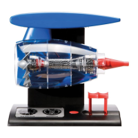
Assembly sequence 4
Assembly sequence 5
Assembly sequence 6
Insert the battery terminals inside
the battery aperture as indicated
Ens ure the terminals with
connection posts are pushed firmly
into their location slots with their
posts protruding through the box
cover
Ensure that the ‘D’ shaped shaft of
the voltage regulator is fully rotated
in a anticlockwise direction before
inserting into the mating aperture of
the control lever.
See assembly sequence 6
Push together and assemble the
lever arms, ensuring that they are
both aligned as shown, and push
the ‘D’ shaped shaft of the voltage
regulator into the mating aperture
of the right-hand lever arm
jet engine
8
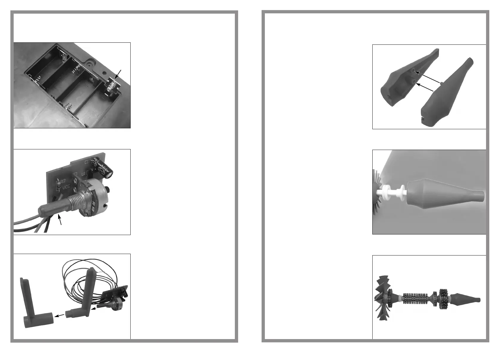
Assembly sequence 55
Assembly sequence 56
Assembly sequence 57
Push the tailcone halves together
Assemble the spacer, washer and
tailcone onto the spindle
Assembled engine fan/turbine/
compressor blade unit
25
 Loading...