AGR Installation and Operation Guide
nautic Laugic www.nauticlaugic.com Page 4
7. Nowevacuateallthepressure-mechanicalcomponentsfromframe.
a. UsingDiagonalCutters,snipthespindle
shaft,andremove.
b. ContinuetoturntheAdjustmentScrew
Counter-Clockwiseuntilit’sloose,and
remove.Saveitsspringandwasher.
c. FindtheRetainingScrewandusea#1
Phillipsscrewdrivertoremoveit.
d. Graspthediaphragmwithpliers,and
removeitsnutwitha7/16”wrench.
RemovetheDiaphragm.
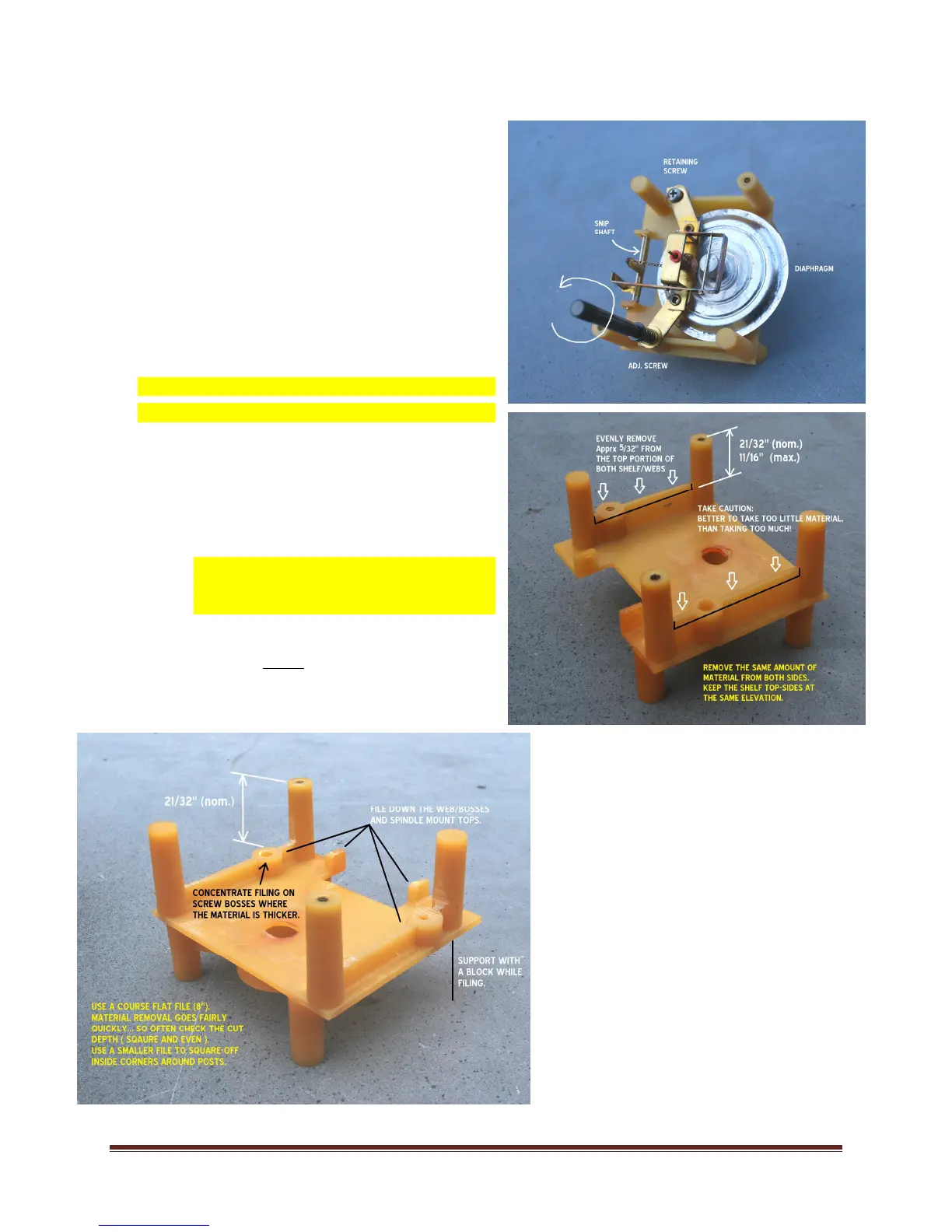
8. Framemodifications:(readtheentiresection
beforebeginning)
a. OBJECTIVEFortheproperrotor-to-dial
registration,theshelves(webs)oneither
sideoftheframemustbereduced.
Removeapproximately5/32”,suchthat
theDialmountingpostsextend21/32”
aboveit.
b. FIRST,withapermanentfinepointpen,
marktheappropriatetargetdepthonthe
websides.
c. Supportthe‘leg-less’cornerwitha
woodenblock.
d. UseacourseFlatFiletoremovetheplastic
web,screw-boss,andspindlemounttops
downtotheprescribeddepth:
Thematerialisrelativelysoft,andisquickly
removedwiththefile…soeasydoesit.Check
yourcutdepthfrequently;erroronthesideof
caution,takelessratherthanmore.Avoid
gettingthewebstooshallow.Thiswillplace
theAGRboardtoolow,allowingtheneedleto
rubonthedial.
e. UseafineFlatFiletosquare
thetopsurfaces:eventhe
cutfrompost-to-post,and
onewebtoanother.
f. SlidetheAGRdownoverthe
dialposts;theAGRwillonly
fitoneway.Inspectthe
framemodificationforaflat,
properfit;tunethe
 Loading...