MODEL / MODELO 9219
5
5084008
Rev. Q 3/16
4
5084008
Rev. Q 3/16
1 5062034B Legs (See Note) 2
2 5062034B Legs (See Note) 2
3 5062031B Handles 2
4 ***** 1/4"-20 x 1 3/4" Bolts 8
5 ***** Hex Nut 1/4"- 20 10
6 5062022B Cross Brace 3
7 5062030B Struts 2
8 ***** 1/4"-20 x 2 1/4" Axle Bolts 2
9 ***** Metal Wheel Spacers 2
10 2011902 Wheels 2
11 2090572 Plastic Caps 4
12 ***** Rubber Spacers 2
13 5010106 Fan Support Knobs 2
14 * Switch Knob 1
15 * Screws 6-32 x 1/4" 1
16 * Motor Cover 1
17 * Switch 1
18 * Cord Set 1
19 * Screws #6 x 5/8" PTH 3
20 02030130 Motor 1
21 05060016 Pivot Bracket w/ Threaded Insert 2
22 5090053 Screws #8-18 x 7/16ty BF PPH 4
23 5097125BK Rear Grill (12 Strut) 1
24 5090045 Screw10-32 x 1/2 HWH SERR F-ZP 3
25 5090044 Set Screw 1/4-28 x 3/8" 1
26 5082045BK Blade 1
27 5097120BK Front Grill (8 Strut) 1
28 5090053 Screws #8-18 x 7/16ty BF PPH 4
29 02084613 Bulls Eye 1
* Included in motor part number 02030130
***** Included in Hardware Bag (Part Number: 2098164A)
Note: See page 5 for Stand Assembly Item Number Identification
to Parts List.
1 5062034B Patas (Vea Nota) 2
2 5062034B Patas (Vea Nota) 2
3 5062031B Asas 2
4 ***** Pernos de 1/4" -20 x 1 3/4" 8
5 ***** Tuerca con Rosca 1/4" -20 10
6 5062022B Barra Transversal 3
7 5062030B Puntales 2
8 ***** Pernos Eje de 1/4" -20 x 2-1/4" 2
9 ***** Espaciadores Metálicos Para las Ruedas 2
10 2011902 Ruedas 2
11 2090572 Tapas Plásticas 4
12 ***** Arandelas de Goma 2
13 5010106 Perillas de Soporte del Ventilador 2
14 * Perilla del Interruptor 1
15 * Tornillo de 6-32 x 1/4" 1
16 * Cubierta del Motor 1
17 * Interruptor 1
18 * Juego de Alambre Flexible 1
19 * Tornillo #6 x 5/8" PTH 3
20 02030130 Motor 1
21 05060016 Soporte Pivote con Inserto 2
22 5090053 Tornillo #8-18 x 7/16ty BF PPH 4
23 5097125BK Rejilla Trasera 1
24 5090045 Tornillo 10-32 x 1/2 HWH SERR F-ZP 3
25 5090044 Tornillo Prisionera de 1/4-28 x 3/8" 1
26 5082045BK Paleta 1
27 5097120BK Rejilla Delantera 1
28 5090053 Tornillo #8-18 x 7/16ty BF PPH 4
29 02084613 Ojo de Buey 1
NO. DE NÚMERO
REF. DE PIEZA DESCRIPCIÓN CANT.
Note: Ver en la página 6 el Ensamblado del Soporte. El Número
de Identificación de cada Artículo está en la Lista de Piezas.
* Incluido en el motor numero de parte 02030130
***** Contenidas en la Bolsa de Piezas. (Número de pieza: 2098164A)
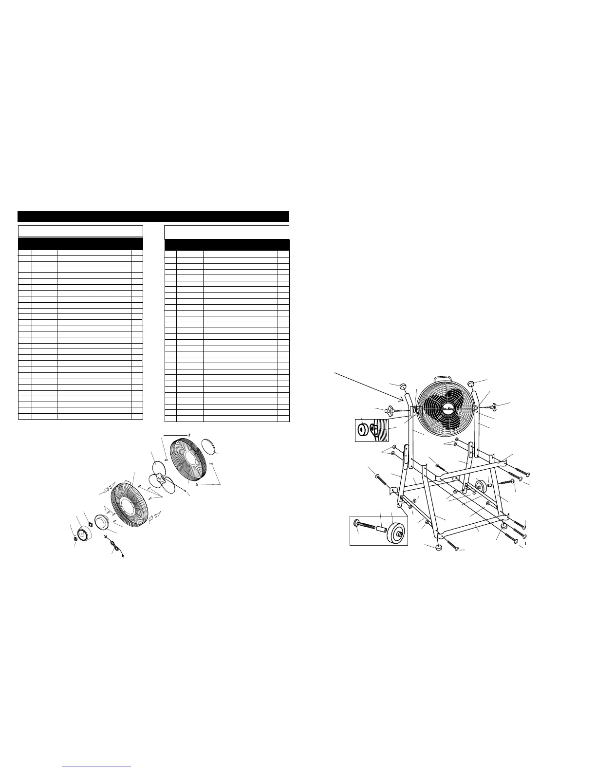
ASSEMBLY
NOTE: For 46" height use lower hole on handle; for 48" height,
use upper hole on handle.
1. Attach one Front Leg (1) and one Back Leg (2) into lower of
two Holes of each Handle (3) using a 1-3/4" Bolt (4) and a
1/4"-20 Nut (5).
2. Connect the two Leg and Handle Assemblies, with one Cross
Brace (6) using a 1-3/4" Bolt (4) and a 1/4"-20 Nut (5) through
the upper Hole in each Handle.
3. Bolt Bottom Cross Braces (6) and Struts (7) together using
the 1-3/4" Bolts (4) and the 1/4"-20 Nuts (5).
4. To attach Wheels, insert 2-1/4" Axle Bolt (8) and Metal Spacer
(9), through Wheel (10), and into the bottom Hole on each
Back Leg. Secure with 1/4" -20 Nuts (5).
NOTE: Lengthened Wheel Hub side goes towards Leg, Spacing
Wheel away from Tube when assembled.
5. Slip Plastic Caps (11) over tubing ends at the top of the
Handles and also at the bottom of the Front Legs.
6. Lay Fan on the floor, front side down.
7. Place Stand on floor, Wheels up, with Handles on each side
of Fan. Align Handle Holes with the Pivot Bracket Assembly
(21) in Rear Grill.
NOTE: Bend of Handle must be toward side of Wheels.
1
1
2
2
3
3
4
4
5
5
6
6
6
5
5
5
4
4
4
8
4
9
10
11
11
11
11
13
13
12
12
5
7
7
21
5
10
9
8
21
12
8. Place Rubber Spacers (12) between the Stand Handles and sides
of the Fan. Then thread Fan Support Knobs (13) through the
Handles and Rubber Spacers into the Pivot Bracket Assembly
in Rear Grill.
9. Check all bolts for tightness.
10. Lift the stand to its upright position.
OPERATION
1. Plug in cord and select desired operating speed with knob on
back of fan.
WARNING: This Fan should be used only in a clean, dry environ-
ment. Mounting this product in any way other then specified in the
instruction sheet will null and void the manufacturers waranty.
MAINTENANCE
WARNING: ALWAYS UNPLUG THE CORD BEFORE SERVICING.
Cleaning: Use a soft cloth and a mild soap solution such as liquid
dish washing detergent.
CAUTION: Do not use gasoline, benzine, thinner, harsh
cleaners, etc. as they will damage the Fan. NEVER use ALCOHOL
OR SOLVENTS.
Dry all parts with a soft cloth completely before reconnecting
to power supply.
STORAGE: When not in use, keep unit in a clean dry place.
DISPOSITION: Corrugated packaging materials are recyclable.
For environmentally responsible disposal of this product, contact
your local waste service provider or visit www.1800recycling.com®.
MOTOR IS PERMANENTLY LUBRICATED.
Ref. Part
No. Number Description Qty.
0
1
2
3
21
28
27
29
28
25
26
23
24
20
19
15
14
21
22
22
16
17
18
19
 Loading...