System Operation
This chapter describes how to use the PGD interface (Table 4-1)to execute the functions needed during
standard operation. This information may be useful during troubleshooting and in conversations with technical
support. For a list of changeable parameters, see Chapter5
System Parameters and Default Values
The following topics are covered:
• Using the Main Menu to execute basic functions
• Understanding alarms that may occur and clearing alarm history
• Additional system diagnostic information
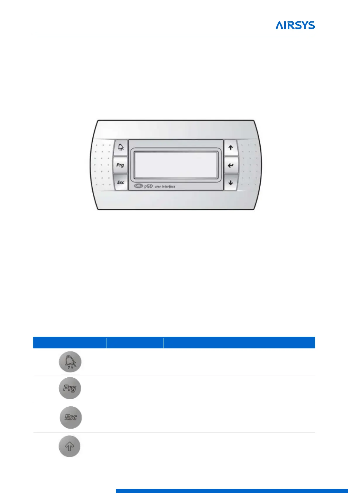
Figure 4-1 PGD User Interface
4.1 User Interface Introduction
The units are controlled using the PGD interface, which has 6 buttons (Figure 4-1). A PGD is preinstalled in
the ASMUC controller which can be used to control all connected WPUs. In addition, a separate PGD can be
connected to a preinstalled display cable on the unit for detailed diagnostics. The preinstalled cable leads from
the J3 connector on the controller module and terminates in the display connector. All settings from the
controller will override settings inputted at the unit unless the unit has been set for standalone operation.
For this section, “controller” will refer to the ASMUC.6 controller box and “system” will refer to the controller
AND all connected units.
Table 4-1 PGD Button Actions
Displays current alarms. Indicates active alarm when
the LED is on.
Enter the menu selection page.
Go up one level in any menu.
Scroll up through menu screens and options
Increase the value of selected parameter