Introduction
1.2 Model Identification
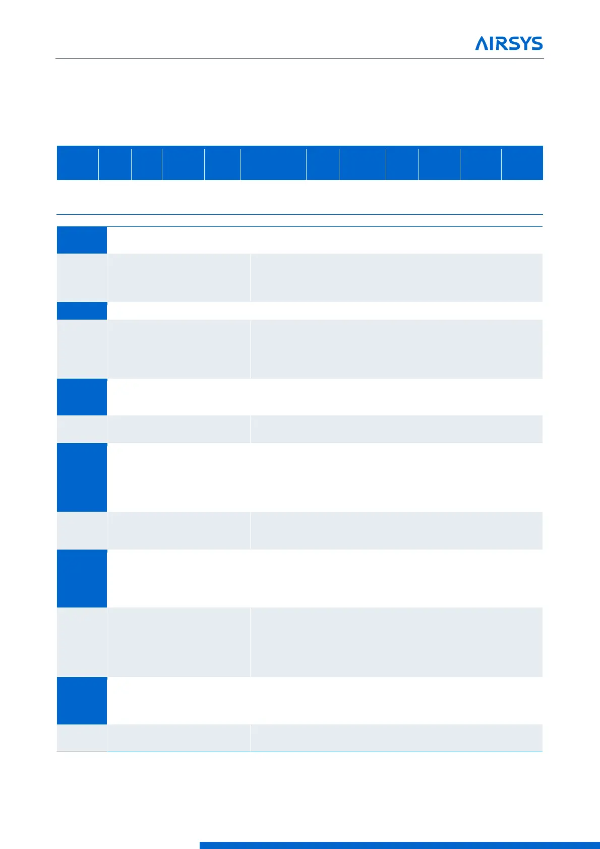
Each unit is identified by a model number, such as 11V1T3MR410AAC. The elements in the number are
explained in Figure 1-1 Model Number
Figure 1-1 Model Number
Nominal kW.
Total Cooling Capacity
Compressor Type:
V: Variable Capacity
E: Fixed Capacity Scroll
R: Fixed Capacity Rotary
Mechcanical Package Code
B: Bottom Supply Package
T: Top Supply Package
The number following“B" or“T”denotes
package size. See mechanical drawing for detail.
Design Control Configuration
M: Designed for Multiple Unit Controller
D: Desgined for Dual (Lead/Lag)Controller
Refrigerant
R410: R410a Refrigerant
Primary Power Supply
A: 208/230V1PH 60Hz
B: 208/230V3PH 60Hz
C: 460V 3PH 60Hz
D: 380V 3PH 50Hz
E: 220V 1PH 50Hz
Supply Fan Power
AC: AC Powered EC Fan
DC: DC Powered EC Fan
Custom Color
X: Mesa Tan (Default)
G: Light Gray
W: White
B: Matte Black
Custom Coating
X: Polyurethane Coated Panel and Frame +
Coated EvaporatorCoil(Default)
C: Default + Blygold CondenserCoilCoating+
Steeless Steel Fasteners
E: Option C + Stainless Steel Panel and Frame
Custom Filters
X: MERV8 (Default)
1: MERV 11
2: MERV 13
Custom Configuration Code
Consult factory for custom configuration