17
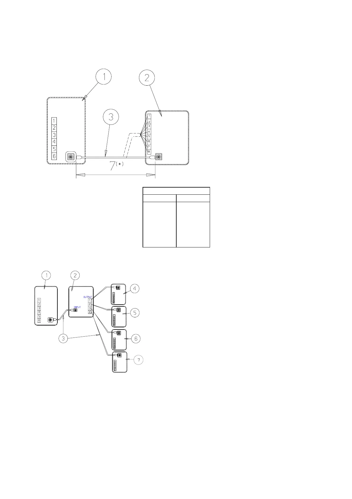
8.3.4 Display unit and master controller mounting
1. Main Control Board on Indoor
Unit
2. Control Display Unit
3. Connection Wire
*Option:
Connecting the cable to control
display terminal
COLOR CHART
Conn. Point Wire Color
1
2
3
4
5
6
7
8
Gold
Green
Black
Brown
Purple
Yellow
Orange
Red
Figure 20. Connection to a single Display Control Unit
1. Main Control Board on Indoor Unit
2. Distribution Board, Cat N. 402729
3. Communication cable Cat. N. 402730
4. Display Control Unit N. 1 Cat. N. 402713
5. Display Control Unit N. 2 Cat. N. 402713
6. Display Control Unit N. 3 Cat. N. 402713
7. Display Control Unit N. 4 Cat. N. 402713
Figure 21. Connection to 4 Display Control Units in Parallel (optional)
 Loading...