5-6
PERFORMANCE DATA & PRESSURE CURVES
Revision 0
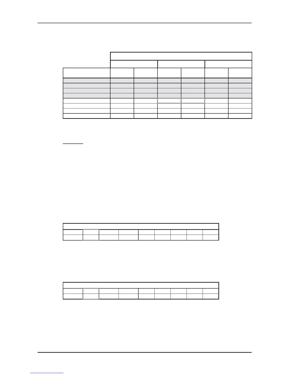
5.4.2 Heating Mode at 7.5m Tubing Connection.
230V : Indoor Fan at High Speed.
ENTERING AIR DB ID COIL ( °C)
15 20 25
ENTERING AIR
WB OU COIL (°C)
TH PI TH PI TH PI
-10 1.58 0.68 1.52 0.72 1.46 0.76
-7 1.70 0.70 1.64 0.74 1.58 0.78
-2 1.80 0.71 1.74 0.75 1.68 0.79
2 2.19 0.74
2.10 0.79
2.01 0.83
6 3.09 0.79 3.00 0.85 2.90 0.90
10 3.36 0.84
3.27 0.90
3.18 0.96
15 3.63 0.88 3.54 0.94 3.45 1.00
20 3.83 0.90 3.74 0.98 3.63 1.05
* the above chart includes the weighted deicing infleuence.
LEGEND
TH – Total Heating Capacity, kW
PI – Power Input, kW
WB – Wet Bulb Temp., (
o
C)
DB – Dry Bulb Temp., (
o
C)
ID – Indoor
OU – Outdoor
5.5 Capacity Correction Factor Due to Tubing Length
5.5.1 Cooling
TOTAL TUBING LENGTH (One Way)
3m
7.5m
10m 15m 20m 25m 30m 40m 50m
1.02
1
0.961 0.950 --- --- --- --- ---
* Minimum recommended tubing length between indoor and outdoor units is 3m.
5.5.2 Heating
TOTAL TUBING LENGTH (One Way)
3m
7.5m
10m 15m 20m 25m 30m 40m 50m
1.05
1
0.975 0.961 --- --- --- --- ---
* Minimum recommended tubing length between indoor and outdoor units is 3m.
 Loading...