5-13
PERFORMANCE DATA & PRESSURE CURVES
Revision 0
5.10 FLO 14 N R410A
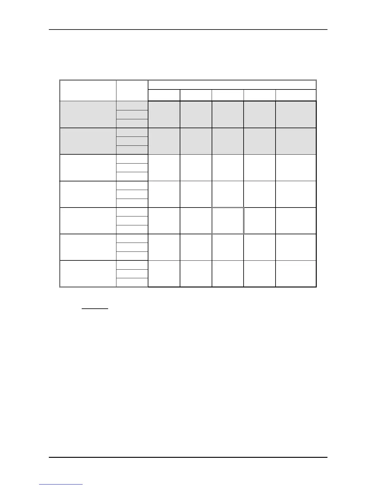
5.10.1 Cooling Mode at 7.5m Tubing Connection.
230V : Indoor Fan at High Speed.
ENTERING AIR
DB OU COIL( °C)
DATA
ENTERING AIR WB/DB ID COIL ( °C)
15/21 17/24 19/27 21/29 23/32
15
(1)
TC
4.22 4.37 4.47 4.58 4.65
SC
2.80 2.92 3.03 3.11 3.17
PI
0.94 0.94 0.95 0.95 0.95
20
(1)
TC
4.08 4.30 4.44 4.54 4.62
SC
2.75 2.89 3.02 3.10 3.16
PI
1.02 1.03 1.03 1.04 1.04
25
TC
3.86 4.17 4.38 4.51 4.62
SC
2.67 2.84 2.99 3.08 3.14
PI
1.11 1.11 1.12 1.13 1.14
30
TC
3.61 3.93 4.25 4.40 4.53
SC
2.59 2.75 2.93 3.01 3.07
PI
1.19 1.21
1.22
1.23 1.24
35
TC
3.34 3.63
4.00
4.20 4.40
SC
2.46 2.64 2.86 2.94 3.00
PI
1.29 1.31
1.33
1.34 1.35
40
TC
3.04 3.31
3.61
3.95 4.15
SC
2.32 2.50 2.71 2.79 2.85
PI
1.39 1.41 1.43 1.45 1.47
46
TC
2.64 2.88 3.17 3.50 3.77
SC
2.14 2.29 2.47 2.55 2.61
PI
1.52 1.54 1.57 1.60 1.62
LEGEND
TC – Total Cooling Capacity, kW
SC – Sensible Capacity, kW
PI – Power Input, kW
WB – Wet Bulb Temp., (
o
C)
DB – Dry Bulb Temp., (
o
C)
ID – Indoor
OU – Outdoor
(1) Marked area is below standard operating limits. For operating in low ambient
conditions, refer to Optional Accessories (Chapter 14).
 Loading...