Do you have a question about the Airwell XLM12RCA and is the answer not in the manual?
Covers refrigerant line installation, leak testing, evacuation, and charging.
Standards for electrical installation, cable sizing, and low voltage wiring.
Criteria and graphs for selecting supply cable sizes based on load, installation, and run length.
Wiring diagram and instructions for single-phase single-system connections.
Wiring diagram and instructions for duo and quattro single-phase systems.
Verifies electrical integrity, visual checks, and fan/ducting for installation compliance.
Checks fan, compressor, refrigeration system, electrical points, and final installation details.
A detailed checklist covering electrical, drainage, refrigeration, and component checks.
Details the sequence of actions and indicators during the self-test mode.
Explains LED flash codes, continuous flashes, and diagnostic logic for sensor faults.
| Cooling Capacity | 3.5 kW |
|---|---|
| Heating Capacity | 3.8 kW |
| Energy Efficiency Ratio (EER) | 3.21 |
| Coefficient of Performance (COP) | 3.61 |
| Power Supply | 220-240V, 50Hz |
| Refrigerant | R410A |
| Indoor Unit Weight | 9 kg |
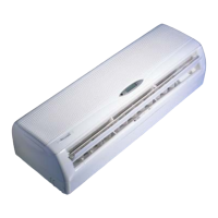
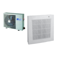
| Type | Split System |
| Power Consumption (Cooling) | 1090 W |
| Outdoor Unit Dimensions (W x H x D) | 780 x 540 x 240 mm |