B. OEM TOP/DOWN MOUNTING
IMPORTANT!
When using this method of rooftop unit installation, an electric
heat elment must not be installed. If an electric heater is to be
installed, the standard interior frame mounting method must be
used to allow access to the heater from below.
When using this top-down installation method, the
vehicle roof must be designed to adequately support and
securely fasten the rooftop unit.
Conrm that the mounting hole area has been properly
prepared.
Refer to OEM Ducting Requirements for proper duct
sizing. The OEM ducting requirement document is
available at www.AIRXCEL.com. The rooftop unit must
be mounted as near to level from front to rear and side
to side as possible. See Figure 3 for maximum allowable
degree deviations.
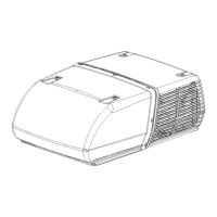
1. Remove rooftop unit plastic shroud, retaining the
hardware.
2. If needed, install foam gasket strip to bottom of unit
basepan or to top of roof structure to separate supply
and return air ductwork.
3. Apply silicone to the bottom of the rooftop unit 14 X 14
gasket and align over the opening in the vehicle roof for
installation.
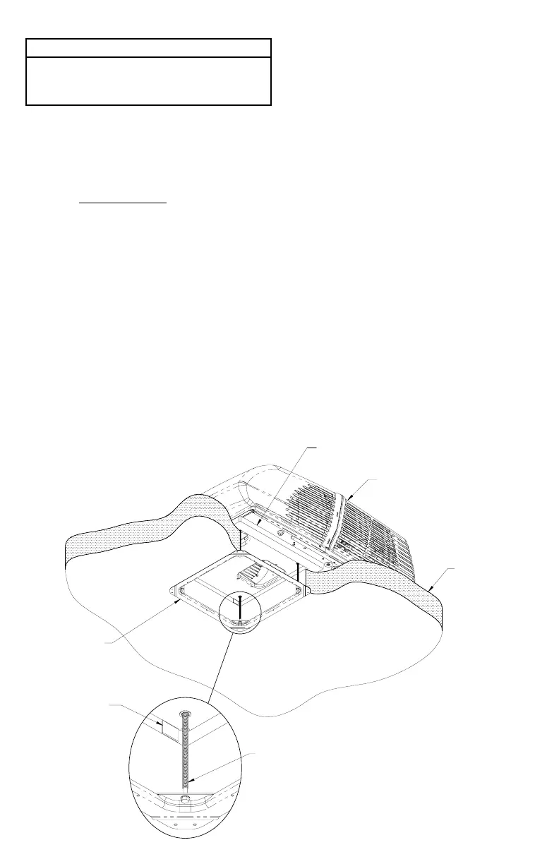
4. Using 4 mounting screws and sealing washers,
run the screws down through the 2 bulkhead ange
holes, 2 front mounting brackets and into the vehicle
roof. Tighten rear screws just until the rear base
base pads contact roof surface (assuming a at roof
surface. Large radius roofs may require additional
support gaskets provided by the OEM.) Tighten the
front screws until the unit gasket has been evenly
compressed. Use care to NOT STRIP the screws. See
Figure 5 and 6.
5. Apply silicone to the top of each mounting screw head.
Re-install the rooftop unit plastic shroud.
V. ELECTRICAL WIRING
ROUTING 115 VAC WIRING
Following Airxcel’s high voltage wiring specications and all
local and national electrical codes, route the roof top unit 115
VAC supply wiring from its power source to the wirebox.
High Voltage Wiring Specications based on Minimum
Overcurrent Protection Device Amperage – (see upper
unit nameplate)
1. U.L. requires copper conductors only with minimum
#12 AWG when using the minimum recommended
overcurrent protection device. Higher rated devices
or longer wiring runs will require #10 AWG or greater
copper conductors.
2. To prevent voltage drops greater than 10% during
starting loads, adhere to the following guideline:
For lengths greater than 50’, use #10 AWG or
larger copper conductors. Match to the overcurrent
protection device provided.
Circuit Protection – Refer to upper unit nameplate.
Electrical Wiring High Voltage Wiring Specication
is based on Overcurrent Protection Device rated
higher than the minimum required (see upper unit
nameplate).
Follow all local and NEC (National Electrical Code)
for proper sizing of wire AWG based on Overcurrent
Protection Device selected and the length of the
wiring run to the Heat Pump.
ROOFTOP UNIT
MOUNTING BOLT
GASKET
INDICATING
TAB
FIGURE 4
4
 Loading...