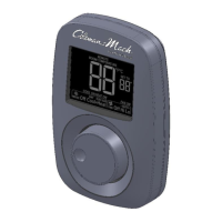
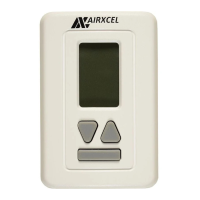
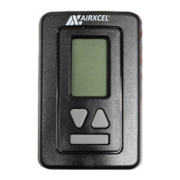
INSTALLATION, OPERATION & APPLICATION GUIDE FOR DIGITAL WALL
THERMOSTAT 9420*381 & 9420*382
WARNING!
This appliance is not intended for use by
young children or inrm persons unless they
have been adequately supervised by a
responsible person to ensure they can use the
appliance safely.
CAUTION!
This thermostat should be installed by trained
technicians only. Adhere to all local and
naonal codes and ordinances.
DISCONNECT ALL POWER TO THE SYSTEM
BEFORE INSTALLING, REMOVING, OR
CLEANING.
Features
The thermostat wiring is factory installed
by the OEM (Original Equipment
Manufacturer). RV Products suggests the
thermostat wiring be a minimum of 20
gauge. The thermostat is intended for use
with a 12 VDC control circuit that does not
exceed 2 amps.
The thermostat is equipped with a self-
reseng PTC fuse located in the
thermostat. The fuse is designed to “open”
if the circuit is mis-wired or if there is a
short in the system.
If the PTC fuse connues to “open”, the
fault must be located and corrected.
The thermostat includes a mounng plate,
2 screws and 2 wall anchors.
An oversized accessory wall plate
(9420*3501) is available for purchase if
needed.
Thermostat and Room Temperature
Sensor Locaon
• An internal temperature sensor on the
thermostat can act as the room sensor.
• Alternavely, a remote temperature
sensor can be connected to the
thermostat to the SENS connectors. The
thermostat will show “REMOTE” at the
top of the display. This situaon would
allow the thermostat to be located
virtually anywhere in the coach, as long
as the user can access the thermostat to
operate it.
The Remote Room Sensors available are
8330-5191 (white) and 8330-3101
(black).