EasyManua.ls Logo

Airxcel 9630-352 User Manual

Airxcel 9630-352
2 pages
To Next Page IconTo Next Page
Page #1 background imageLoading...
Page #1 background image
A. THERMOSTAT LOCATION
This thermostat is a sensitive instrument. For accurate temperature control and comfort, the
following considerations should be taken into account:
1. Locate the thermostat on an inside wall about ve feet above the oor.
Pick a dry area where air circulation is good.
2. Do not install thermostat where there are unusual heating
conditions, such as direct sunlight, near heat producing
appliances (televisions, radio, wall lamp, etc.), or a furnace or air
conditioner supply register.
B. INSTALLING THE THERMOSTAT
1. Place mounting screw template against the wall where thermostat will
be mounted.
2. Using supplied screws, mount the template to the wall.
3. Remove plastic from between mounting screws.
4. Connect thermostat wiring to motorcoach wiring.
5. Place thermostat on mounting screws and gently push the thermostat
down to lock the thermostat onto mounting screws.
6. Turn on power to the thermostat.
Caution
This thermostat should be installed by trained technicians only. Adhere to all local and national
codes. Disconnect all power to the system before installing, removing, or cleaning.
Button Functions
UP – Wake thermostat and increase temperature
DOWN – Wake thermostat and decrease temperature
MODE – Wake thermostat, change mode
Note: Hold mode button down for 5 seconds. The thermostat will change from fahrenheit to
celsius or celsius to fahrenheit. The backlight will turn off after ve seconds.
Operation
The display indicates the mode and the room temperature. When the mode button is pressed
once, the thermostat will wake and if your thermostat is equipped with a backlight, the backlight
will illuminate. When the mode button is pressed again, the mode will change. Press the or
button to wake the thermostat, the set temperature will display and ash. Press the or
button again to change the set temperature. The thermostat will go back to sleep mode after 5
seconds if no buttons are pressed.
In electric heat mode, if the heat pump is unable to satisfy the thermostat call, the heat pump
will go into lockout (See heat pump and backup heat example for conditions of heat pump
lockout). When thermostat is in lockout, ELEC will ash on the display.
In gas heat mode, the gas furnace will provide the only source of heat and the heat pump is
locked out.
Temperature
Mode
Range
°F °C
Cooling (set) 33°F to 99°F 1°C to 37°C
Heating (set) 33°F to 99°F 1°C to 37°C
Refer to the operation chart for a more detailed listing of operation sequence.
INSTALLATION, OPERATION
& APPLICATION GUIDE
HEAT PUMP
9630*352*
The thermostat wiring is factory installed by the OEM (Original Equipment Manufacturer). RV
Products suggests the thermostat wiring be a minimum of 18 gauge. The thermostat is intended
for use with a 12 VDC control circuit that does not exceed 1 amp. The thermostat is equipped
with a replaceable 2 amp fuse located on the base of the thermostat. The fuse is designed to
“open” if the circuit is mis-wired or if there is a short in the system. Before replacing the fuse, the
cause of the failure must be located and corrected.
Application
Installation
ELECTRICAL SHOCK HAZARD – Turn off power at the main service panel by
removing the fuse or switching the appropriate circuit breaker to the Off position
before removing the existing thermostat.
05-03-18
1. Download the RVClimate app from either the
Google Play store or Apple App store.
2. Open the app and select “ADD NEW
THERMOSTAT”.
3. On the thermostat, hold the Up and Down
buttons simultaneously to enter pair mode.
4. On the App select “PAIR NEW
THERMOSTAT”.
5. When prompted, enter the 6 digit ID from the
thermostat and select “PAIR”.
6. Once connected the thermostat will revert to
the main screen.
7. Slide screen to the left (2nd screen).
8. Press .
9. Select “ZONE NAME”.
10. Assign a name or description to the thermostat
(7 characters max).
11. Select SET” to save the assigned name or
description.
Note: Each thermostat may be connected
to a maximum of 4 individual phones.
Any subsequent connections will
result in the oldest/first connections being automatically deleted in order.
Pairing additional thermostats
1. Using the RVClimate app.
2. Slide screen to the left (last screen).
3. Select “PAIR NEW THERMOSTAT”.
4. On the thermostat, Hold the Up and Down buttons simultaneously to enter pair mode.
5. When prompted, enter the 6 digit ID from the thermostat and select “PAIR”.
6. Once connected the thermostat will revert to the main screen.
7. Slide screen to the left (2nd screen).
8. Press .
9. Select “ZONE NAME”.
10. Assign a name or description to the thermostat (7 characters max).
11. Select “SET to save the assigned name or description.
Note: A maximum of 3 units may be added to an individual phone.
Pairing a previously paired thermostat
1. Using the RVClimate app select ADD NEW THERMOSTAT”.
2. On the thermostat, Hold the Up and Down buttons simultaneously to enter pair mode
3. Thermostat will automatically pair.
Note: If thermostat doesn’t pair automatically, when prompted enter the 6 digit ID from the
thermostat and select “PAIR”.
4. Once pairing is complete, press the thermostat’s mode button to return to the main screen.
Pairing the Thermostat
Wiring Diagrams
Green
Gray
Wht/Blk
2
3
1
4
Fan Hi
Heat Pump
Fan Lo
M
Plug Housing
Amp P/N: 1-480702-0
Pin Terminal x2
Amp P/N: 350218-1
F
Cap Housing
Amp P/N: 1-480703-0
Socket Terminal x4
Amp P/N: 350536-1
From thermostat 9630*352*
Y
R
B
W
White
Red
Blue
Yellow
2
3
1
4
Furnace
+12 VDC
-12 VDC
Compressor
WHP
GH
GL
Note: When used to replace a thermostat which previously did not use plugs,
please remove the plugs and use wire nuts as needed.
Question and Answer IconNeed help?

Do you have a question about the Airxcel 9630-352 and is the answer not in the manual?

Airxcel 9630-352 Specifications

General IconGeneral
BrandAirxcel
Model9630-352
CategoryThermostat
LanguageEnglish

Summary

Wiring Diagrams

Caution and Safety

General Caution

Thermostat installation should be done by trained technicians adhering to all codes. Disconnect power before installation or removal.

Application and Operation

Thermostat Application

Designed for 12 VDC control circuits not exceeding 1 amp, equipped with a replaceable 2 amp fuse for system protection.

Thermostat Operation Modes

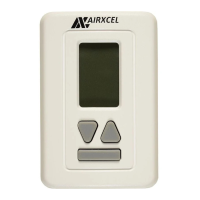
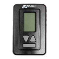
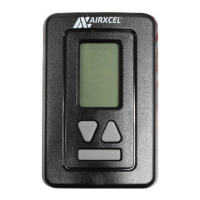
Explains display, wake function, temperature adjustment, and mode changes, including electric and gas heat behavior.

Button Functions

Details the UP, DOWN, and MODE buttons for waking the thermostat and adjusting settings, including Fahrenheit/Celsius conversion.

Installation Guide

Electrical Shock Hazard

Turn off power at the main service panel before removing or installing the thermostat to prevent electrical shock.

Thermostat Location Selection

Choose an inside wall, five feet above the floor, in a dry area with good air circulation, away from heat sources.

Thermostat Mounting Steps

Use template to mount, connect wiring, attach thermostat to screws, and secure it to the mounting base.

Thermostat Pairing

Initial Thermostat Pairing

Guide to pairing the thermostat with the RVClimate app using a 6-digit ID, including zone naming and saving settings.

Pairing Additional Thermostats

Instructions for adding more thermostats to the RVClimate app, up to 3 units per phone, using a 6-digit ID.

Re-pairing a Thermostat

Steps for re-pairing a previously connected thermostat, which may involve entering the 6-digit ID if auto-pairing fails.

Detailed Operation and Troubleshooting

Thermostat Control Via App

How to control temperature and modes remotely using the RVClimate app, including selecting desired settings.

Removing a Paired Thermostat

Procedure to remove a thermostat from the RVClimate app by selecting 'REMOVE THERMOSTAT' on the app.

Conditions of Heat Pump Lockout

Details temperature thresholds and conditions that cause heat pump lockout, including strikes and backup heat activation.

Operation Chart

Lists various modes (Cool, Heat) with call signals (Yes/No) and corresponding wire operations (e.g., GL-Fan Low, WHP).

Backup Counter Reset

Explains how the backup counter resets when the heat pump runs for 20 minutes without needing backup heat.

Related product manuals