5
CHLORINE GENERATOR INSTALLATION
FITTING THE CHLORINATOR CELL HOUSING
The Pixie™ cell housing must be plumbed into the return line of the pool fi lter system after the
fi lter and any diversion valves. Please refer to the installation diagram for the correct method of
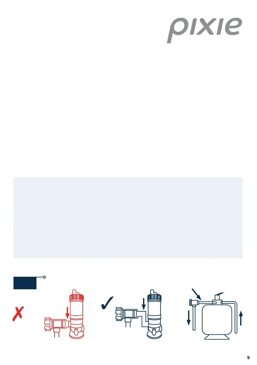
installation (Fig. 3) and note installation of a gas trap below (Fig. 2).
In situations where a heater is incorporated, the Pixie™ housing must be installed after or in
parallel to the heater. Should a solar heating system be installed, the housing must be plumbed
after the solar diverters and before the heated water rejoins the main pool return line.
Please note that your cell housing has been manufactured so that 40 mm PVC pipe will fi t both
inlet and outlet ports internally, and 50 mm couplings will fi t externally. This allows the use of
either 40 mm or 50 mm PVC pipes in the pool return line.
GAS TRAP
NO GAS TRAP
Gas trap - the cell housing must be installed to form a gas trap as shown below.
If water was to stop fl owing and the chlorine generator continue running, gas pressure
will build up in the housing and pipe work and cause damages. This can happen if water
continues to run back into the electrode housing (e.g. from an outgoing pipe after the
pump is turned o ), allowing water to come in contact with the electrodes producing
a build-up of gas. A gas trap allows the gas to displace water away from the sensor
terminal, thus turning o the Chlorine generator power supply. In this scenario, status
light 3 will fl ash and alarm will sound.
Fig. 2