EasyManua.ls Logo

Aiwa CSD-A120 Series User Manual

Aiwa CSD-A120 Series
35 pages
To Next Page IconTo Next Page
Page #1 background imageLoading...
Page #1 background image
SERVICE MANUAL
DATA
BASIC TAPE MECHANISM : TN-9ZR-219
BASIC CD MECHANISM : DA11T3C
COMPACT DISC STEREO
CASSETTE RECEIVER
CSD-A120
S/M Code No. 09-014-356-0N1
U(S),K(S)
EZ(S),LH(S)
HRJ(L),HRJ(P)
HS(S),HRJ(S)
LH(S)
CSD-A140
Question and Answer IconNeed help?

Do you have a question about the Aiwa CSD-A120 Series and is the answer not in the manual?

Aiwa CSD-A120 Series Specifications

General IconGeneral
BrandAiwa
ModelCSD-A120 Series
CategoryReceiver
LanguageEnglish

Summary

Service Manual

Model Identification

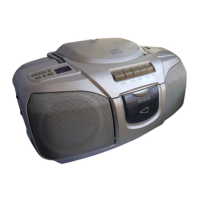
Specifies the models covered: CSD-A120 and CSD-A140.

Product Type

Identifies the unit as a Compact Disc Stereo Cassette Receiver.

Specifications

120HR, K, E, HS Model Specifications

Technical details for the 120HR, K, E, and HS models.

120LH, 140LH Model Specifications

Technical details for the 120LH and 140LH models.

120U Model Specifications

Technical details for the 120U model.

Laser Safety Precautions

Laser Beam Exposure Warnings

Important safety information regarding laser beam exposure during servicing.

Optical Block Replacement Precautions

Electrostatic Discharge (ESD) Precautions

Guidelines to prevent damage to the laser diode from static electricity.

Electrical Main Parts List - Part 1

Electrical Main Parts List - Part 2

Electrical Main Parts List - Part 3

Chip Resistor Part Coding

Explanation of the coding system for chip resistors.

Block Diagram - Part 1/2

Block Diagram - Part 2/2

Wiring Diagram - Part 1/4

Wiring Diagram - Part 2/4

Wiring Diagram - Part 3/4

Wiring Diagram - Part 4/4

Model Specific Wiring

Wiring details specific to U, EZ, K, HS and LH, HRJ models.

Schematic Diagram - Part 1/3

Schematic Diagram - Part 2/3

Schematic Diagram - Part 3/3

Transistor Illustrations

IC Block Diagrams

Voltage Chart - Part 1/2

Voltage Chart - Part 2/2

Electrical Adjustments - Part 1/2 (U Model)

Tuner Section Adjustments

Adjustment procedures for the tuner section of the U model.

Deck Section Adjustments

Adjustment procedures for the deck section of the U model.

Electrical Adjustments - Part 2/2 (Except U Model)

Tuner Section Adjustments

Adjustment procedures for the tuner section of models other than U.

Deck Section Adjustments

Adjustment procedures for the deck section of models other than U.

IC LA9250M Pin Descriptions - Part 1/2

IC LA9250M Pin Descriptions - Part 2/2

IC LC78602E Pin Descriptions - Part 1/2

IC LC78602E Pin Descriptions - Part 2/2

Mechanical Exploded View

Mechanical Parts List

Color Name Table

Tape Mechanism Exploded View

Tape Mechanism Parts List

CD Mechanism Exploded View

CD Mechanism Parts List

Accessories/Package List

Company Information

Related product manuals