Do you have a question about the Aiwa CSD-TD49LHW and is the answer not in the manual?
Specifications for power, dimensions, and weight across different models.
Important safety warnings and cautions regarding laser exposure during servicing.
Measures to prevent electrostatic discharge from damaging the laser diode during replacement.
Block diagram illustrating interconnections between CPU, CD control, and CD sections.
Block diagram showing connections for Main, Cassette, Power Amp, and Tuner sections.
Detailed schematic for the Main and CD Circuit Boards (part 1/2).
Detailed schematic for the CD Circuit Board (part 2/2), including ICs and connections.
Schematics for the Front, Remote Control, and Deck Circuit Boards.
Detailed schematic for the Tuner Circuit Board, including ICs and components.
Schematic for Power and Battery Boards, showing AC input and battery connections.
Procedures for adjusting Tuner AM VT and FM VT using a multimeter.
Procedures for AM IF adjustment using L006 and AM tracking adjustment using L003/TC001.
Procedure for FM tracking adjustment using L002, requiring an oscilloscope.
Procedures for Tape Speed, Wow-flutter, and Head Azimuth adjustments for the tape deck.
Procedures for checking CD RF waveform, jitter, tracking balance, and playback ability.
| CD Player | Yes |
|---|---|
| Cassette Player | Yes |
| Anti-Skip Protection | No |
| Playback Formats | CD |
| Power Source | AC 230V |
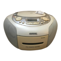
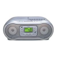
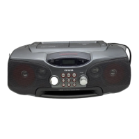
| Type | Portable CD/Radio Cassette Recorder |