EasyManua.ls Logo

Aiwa CX-75 User Manual

Aiwa CX-75
30 pages
To Next Page IconTo Next Page
Page #1 background imageLoading...
Page #1 background image
S/M
Code
No.89-074
DATE
OF
ISSUE
8,/1989
|
Ore
AIWA’
ERVIGE
MANUAL
e
BASIC
TAPE
MECHANISM
:
i
=
ee
Te
K)
e
TYPE.
EKZ
*%3
RC
T75F
PX
E75
DX
M75
(OPTIONAL)
*%3
RC
T75F
DX
—-
M75
(OPTIONAL)
CP
—75
CP
-75
1
CP—75
does
not
have
SX
705.
STEREO
SYSTEM
SPEAKER
SYSTEM
REMOTE
CONTROLLER
SYSTEM
|
CASSEIVER
X-
75
X-7
CP
75
X-7
*%3
DX
M75
(OPTIONAL)
XK
3
DX
M75
(OPTIONAL)
x2
As
to
the
service
information
of
PX
E75.
See
The
individual
service
mamual
of
PX
E75/E45.
x3
As
to
the
service
information
of
DX
M75.
See
The
individual
service
mamual
of
DX
M75//M76.
AIWA
Co.,
Ltd.
:
Tokyo
Japan
Printed
in
Japan
ag
Question and Answer IconNeed help?

Do you have a question about the Aiwa CX-75 and is the answer not in the manual?

Aiwa CX-75 Specifications

General IconGeneral
BrandAiwa
ModelCX-75
CategoryStereo System
LanguageEnglish

Summary

System Specifications

CX-75 Receiver Specifications

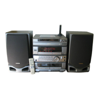
Details power source, output, frequency response, and signal-to-noise ratio for the CX-75 receiver.

SX-705 Speaker Specifications

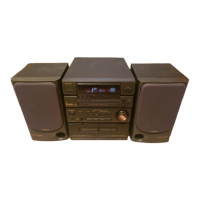
Specifies speaker type, impedance, input, dimensions, and weight for the SX-705 speaker system.

IC Descriptions

LC7230-8239 Pinout and Description

Lists pin numbers, names, I/O, and function descriptions for the LC7230-8239 IC.

LC7230-8239 LCD Control

Electrical Main Parts List

System Block Diagram

Wiring Diagrams

Main, Tuner, and Power Circuit Board Wiring

Shows the physical layout and wiring connections for key circuit boards.

Schematic Diagrams

Main and Tuner Circuit Board Schematics

Presents detailed electronic circuit schematics for the main and tuner boards.

Front Circuit Board Schematic and Service Information

IC Block Diagrams

Illustrates block diagrams for key integrated circuits, aiding in functional understanding.

Practical Service Figures

Details performance figures and adjustment points for Tuner and Cassette sections.

Additional Circuit Schematics and Service Data

Lamp and Front Circuit Board Schematics

Details schematics for lamp control and front panel circuitry.

IC Block Diagrams

Illustrates block diagrams for integrated circuits, clarifying their roles.

Practical Service Figures

Provides detailed performance figures and adjustment points for various system sections.

Adjustments

Tuner Section Adjustments

Guides for adjusting tuner clock frequency, VT settings, tracking, and IF.

Deck Section Adjustments

Procedures for tape speed, head azimuth, and sensitivity adjustments for the deck.

Exploded Views and Parts Lists

Exploded View 1

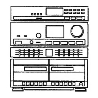
Visual representation of external components and assembly for the system.

Mechanical Parts List

Lists mechanical components with part numbers and descriptions for repair.

Exploded View 3 (E1,K)

Detailed view of E1,K model components and assembly for parts identification.

Exploded View 4 (E,Z)

Detailed view of E,Z model components and assembly for parts identification.

Speaker List

Accessories and Package List

Related product manuals