EasyManua.ls Logo

Aiwa CX-JN3 Service Manual

Aiwa CX-JN3
76 pages
To Next Page IconTo Next Page
Page #1 background imageLoading...
Page #1 background image
SERVICE MANUAL
Model Name Using Similar Mechanism NEW
CD Mechanism Type
CDM74-K6BD71A, CDM74S-K6BD71A,
CDM74S-K6BD72
CD
Base Unit Name BU-K6BD71A, BU-K6BD72
Section
Optical Block Name KSM-213DCP
Optical Pick-up Name KSS-213D
Tape deck
Model Name Using Similar Mechanism NEW
Section
Tape Transport Mechanism Type CWM43FF13, CWM43FF25
COMPACT DISC DECK RECEIVER
US Model
AEP Model
UK Model
E Model
CX-JN3
Ver. 1.2 2005.05
9-877-248-03 Sony Corporation
2005E05-1 Personal Audio Group
© 2005.05 Published by Sony Engineering Corporation
SPECIFICATIONS
CX-JN3 is the amplifier, CD player, tape deck
and tuner section in JAX-N3/PK3.
TUNER
FM tuning range
87.5 MHz to 108 MHz
FM usable sensitivity (IHF)
13.2 dBf
FM
antenna terminal 75 ohms (unbalanced)
AM
tuning range 530 kHz to 1710 kHz (10 kHz step)
531 kHz to 1710 kHz (9 kHz step)
AM usable sensitivity
350 µV/m
AM antenna
Loop antenna
AMPLIFIER
Power output
40 W + 40 W (40 Hz - 20 kHz, THD
less than 1 %, 6 ohms)
50 W + 50 W (1 kHz, THD less than
10 %, 6 ohms)
Total harmonic distortion
0.08 % (20 W, 1 kHz, 6 ohms)
Input
VIDEO/AUX: 400 mV
Outputs
SPEAKERS: 6 ohms or more
PHONES: 32 ohms or more
CASSETTE DECK
Track format
4 tracks, 2 channels stereo
Frequency response
50 Hz – 8 kHz
Recording system
AC bias
Heads
Deck A: playback x 1
Deck B: recording/playback x 1,
erase x 1
CD PLAYER
Laser Semiconductor laser ( λ = 780 nm)
Emission duration:
continuous
D/A converter 1 bit dual
Signal-to-noise ratio 85 dB (1 kHz, 0 dB)
Harmonic distortion 0.05 % (1 kHz, 0 dB)
GENERAL
Power requirements 120 V AC, 60 Hz
Power consumption 65 W
Power consumption With ECO mode on: 0.25 W
in standby mode With ECO mode off: 15 W
Dimensions (W x H x D) 280 x 330 x 392.5 mm
(11
1
/
8
x 13 x 15
1
/
2
in.)
Weight 6.7 kg (14 lbs 12 oz)
Specifications and external appearance are subject to change
without notice.
COPYRIGHT
Check copyright laws relevant to recordings from discs,
or tape for the country where the unit is to be used.
Licensed by BBE Sound, Inc. under USP4638258, 5510752
and 5736897.

Table of Contents

Question and Answer IconNeed help?

Do you have a question about the Aiwa CX-JN3 and is the answer not in the manual?

Aiwa CX-JN3 Specifications

General IconGeneral
BrandAiwa
ModelCX-JN3
CategoryStereo System
LanguageEnglish

Summary

Servicing Notes

Optical Pick-up Handling Precautions

Essential precautions for handling optical pick-up blocks, preventing ESD and physical damage.

Laser Diode Emission Check Guidelines

Correct procedures for safely checking laser diode emission from the optical pick-up block.

Unleaded Solder Information

Details on the characteristics, application, and handling of unleaded solder.

General Information

Location of Controls Overview

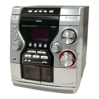
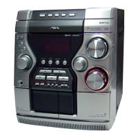
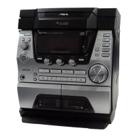
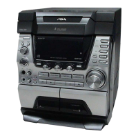
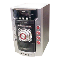
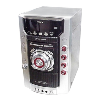
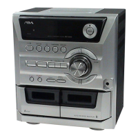
Identifies and describes all front and rear panel controls and connectors for user operation.

Disassembly Procedures

Disassembly Flow Chart

A sequential diagram outlining the steps for disassembling the entire unit.

Case Disassembly Procedures

Step-by-step instructions for removing the unit's outer case panels (side and top).

CD Mechanism Deck Removal

Guide for safely detaching and removing the CD mechanism deck assembly.

Front Panel Section Removal

Instructions for disassembling and removing the front panel section.

PT and Main Board Removal

Procedure for detaching the PT and Main circuit boards from the chassis.

Test Modes

MC Cold Reset Procedure

Steps to perform a cold reset, clearing all stored data and returning to initial settings.

GC Test Mode Operation

Guide for activating and utilizing the GC test mode for system diagnostics.

AMP Test Mode Operation

Instructions for entering and operating the AMP test mode for audio amplifier functions.

CD Repeat Limit Cancel Mode

Procedure to enable unlimited CD playback repeat by canceling the standard 5-time limit.

CD Test Mode Operations

Details on using CD test mode for sled motor control and pickup maintenance.

Electrical Adjustments

S-Curve Check Procedure

Method for verifying CD player S-curve waveform symmetry and peak level.

RF Level Check Procedure

Procedure to confirm the clarity and correct signal level of the CD player's RF output.

Diagrams and Schematics

CD Section Block Diagram

Functional block diagram illustrating signal flow within the CD player circuitry.

Main Section Schematic (1/4)

First part of the detailed schematic diagram for the main circuit board.

IC Pin Function Descriptions

Detailed explanation of pin functions for various integrated circuits used in the unit.

Exploded Views

Exploded View: Case Section

Illustrated breakdown of the unit's case components for assembly/disassembly.

Exploded View: Front Panel Sections

Illustrated breakdown of front panel parts, covering multiple views.

Exploded View: CD Mechanism Deck (Part 1)

Illustrated breakdown of parts for the CD mechanism deck, section 1.

Exploded View: Base Unit Section

Illustrated breakdown of the base unit components for assembly/disassembly.

Electrical Parts List

BD Section Parts List

Comprehensive list of electrical components used in the BD section.

Main Section Parts List

Comprehensive list of electrical components used in the main board section.

Panel Section Parts List

Comprehensive list of electrical components used in the panel section.

Motor Section Parts Lists

Lists electrical components for the motor (LD) and motor (TB) sections.

Related product manuals