Do you have a question about the Aiwa CX-JDS55 and is the answer not in the manual?
Information on amplifier power output, inputs, and outputs.
Details regarding the CD player system.
Covers power, dimensions, mass, model identification, and part numbers.
Critical warning about safety-related components and their replacement.
Procedures for S-curve and RFAC signal level checks in the CD section.
Procedure for performing the E-F balance adjustment for the CD section.
Detailed pin functions for IC604 on the Panel Board.
List of capacitors, resistors, transistors, diodes, connectors, and ICs for the AMP board.
Detailed list of resistors and capacitors for the AMP board.
List of capacitors, connectors, diodes, ICs, transistors, and resistors for the BD board.
Parts list for Contact and Main boards including capacitors and connectors.
List of diodes, ICs, transistors, and resistors for the Panel board.
Detailed list of resistors for the Panel board.
Parts list for PAI/HP/MIC board including resistors, relays, switches, and capacitors.
List of capacitors, jacks, jumpers, coils, transistors, and resistors for the Panel board.
Parts list for Panel board including terminals, ICs, jumpers, coils, LEDs, and transistors.
Further listing of resistors for the Panel board.
Parts list for Panel and Power boards including resistors, switches, vibrators, and capacitors.
Parts list for Power and Volume boards including connectors, diodes, transformers, relays, switches, wires, LEDs, and resistors.
| Brand | Aiwa |
|---|---|
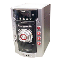
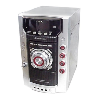
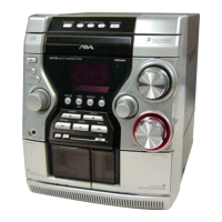
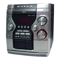
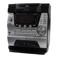
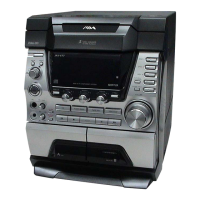
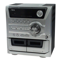
| Model | CX-JDS55 |
| Category | Stereo System |
| Language | English |