Do you have a question about the Aiwa HS-JS380 and is the answer not in the manual?
Steps to detach the rear cabinet by removing screws and releasing clips.
Guide to removing the main C.B by unscrewing and disconnecting wires and connectors.
Procedure to remove the tape mechanism, involving flex cables and solder points.
Instructions for detaching the front C.B by unscrewing and releasing hooks from slots.
Steps for removing the internal microphone assembly, including unscrewing and handling wires.
Detailed procedure for microphone replacement, focusing on soldering points and wire management.
Guidance on reassembling the main board, ensuring proper connector and switch alignment.
Steps for assembling tuning pointer, gear, and knob components for correct operation.
Overview of major functional blocks and their interconnections within the device.
Detailed schematic of specific ICs showing internal functional blocks and pin assignments.
A comprehensive list of electrical components with part numbers and descriptions.
A detailed listing of components specifically for the tape transport mechanism.
Visual representations and pin configurations for key transistors used in the unit.
Detailed circuit schematic illustrating component interconnections and signal paths.
Procedures for tuning AM/FM IF, frequency, and tracking for optimal radio reception.
Steps for adjusting tape speed, including test points and conditions for accurate playback.
An illustrated breakdown of all mechanical parts for assembly and identification.
Diagrams showing the correct placement and orientation of various springs within the mechanism.
| Type | Cassette Player |
|---|---|
| Brand | Aiwa |
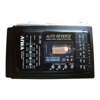
| Model | HS-JS380 |
| Power Source | 2 x AA batteries |
| Mega Bass | Yes |
| Playback Features | Auto-Reverse |
| Headphones Output | 3.5 mm jack |
| Radio | AM/FM |