Do you have a question about the Aiwa HV-BA75 and is the answer not in the manual?
Instructions for removing the top cover of the VCR.
Steps for detaching the front panel assembly.
Procedures for removing Key circuit boards.
Steps to detach the main mechanism and main circuit board.
Specifies where to install spacers for the service position.
Steps for removing the drum assembly.
Steps for removing top plate, holder CST, and guide CST.
Procedures for removing bracket side, door, and arm assemblies.
Steps for disassembling head, brake, and reel components.
Procedures for removing various gears, levers, and tension parts.
Lists necessary tools and devices for performing adjustments.
Procedure to check correct mechanism positioning after ejection.
Steps to set the mechanism for adjustment without a cassette.
Procedure to ensure smooth tape transport by checking reel torque.
Procedure to regulate tape height on the lower drum.
Ensures accurate tape path over audio/control tracks.
Procedure to obtain compatibility with other VCR models.
Corrects roller guide and X-value shifts after drum replacement.
Verifies tape movement and locking times post-reassembly.
Initial checks for cleaning, lubrication, and part condition.
Discusses the precision and importance of VCR component maintenance.
Provides guidelines for periodic inspection based on usage.
Lists necessary consumables like grease and alcohol.
Details specific points for applying grease during maintenance.
Guides through diagnosing and resolving deck mechanism faults.
| Type | VCR |
|---|---|
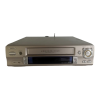
| Brand | Aiwa |
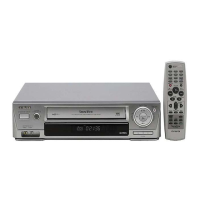
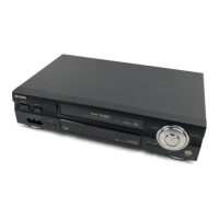
| Model | HV-BA75 |
| Recording System | VHS |
| Heads | 4 |
| Remote Control | Yes |
| Tuner | Yes |
| Playback Speed | SP/LP |
| Inputs | Composite Video, Audio |
| Outputs | Composite Video, Audio |