Do you have a question about the Aiwa HV-GX935 and is the answer not in the manual?
Lists the specific models covered by the manual.
Details the manual's revision status and replacement information.
Technical specifications for HV-FX7700 and HV-BA75 models.
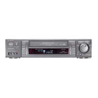
Technical specifications for the HV-GX935 model.
Lists the included accessories for the product.
Procedure for removing the top casing of the unit.
Steps to remove the front panel assembly.
Instructions for removing Key1 and Key2 circuit boards.
Steps to detach the main mechanism from the chassis.
Procedure for removing the Main Circuit Board.
Instructions on how to set the mechanism to the service position.
Specifies the locations for installing adjustment spacers.
Details the types of test tapes and their applications for alignment.
Describes the signals recorded on alignment tapes.
List of integrated circuit components used in the unit.
List of transistors and diodes with part numbers.
List of capacitor components and their specifications.
Parts list for connectors, coils, and related components.
List of transformers, tuners, sensors, and switches.
Visual representations of transistor pinouts.
Table mapping model suffixes to specific units.
Diagram showing the wiring connections for the NICAM C.B.
Wiring diagram for the key input boards.
Harness diagram for drum and motor connections.
Diagram illustrating various power supply voltage circuits.
Explanations for circuit symbols used in diagrams.
Shows the routing of audio signals to and from the connector.
Illustrates the flow of audio signals within the unit.
Details the ICs involved in Hi-Fi audio processing.
Shows how Hi-Fi audio signals connect to other modules.
Block diagram for the LA71598M audio/video processor.
Block diagram for the LC74793 VPS/PDC decoder.
Block diagram for the LA71598M normal audio processor.
Diagram showing normal audio signal paths.
Diagram showing the tuner IC and its connections.
Diagram for the NICAM/A2 IC and its functions.
Block diagram of the main microcontroller IC.
Diagrams for key board, OSD, and other control circuits.
Block diagram of the main microcontroller IC for GX935.
Diagrams for key board, OSD, and other control circuits for GX935.
Detailed schematic of the power supply circuits.
Schematic of the tuner and NICAM sections.
Detailed schematic of the power supply circuits for GX935.
Schematic of the tuner section for GX935.
Voltage readings for key ICs in the power section.
Voltage readings for transistors in the power section.
Voltage chart for IC301 in the audio/video section.
Voltage chart for IC7V1 in the audio/video section.
Voltage charts for transistors in the audio/video section.
Oscilloscope waveforms at various pins of IC301.
Block diagram for IC LC74793.
Schematic of the LA71598M audio/video processing circuit.
Schematic showing Hi-Fi audio signal interconnections.
Schematic of Hi-Fi audio processing ICs (IC801, IC901).
Schematic detailing SCART connector signal paths.
Voltage chart for IC801 in the Hi-Fi audio section.
Voltage chart for IC901 in the Hi-Fi audio section.
Schematic of the SCART section for the HV-GX935.
Block diagram for the MM1443XJ IC.
Voltage chart for the main microcontroller IC501.
Voltage charts for other ICs in the control/servo section.
Schematic of the main microcontroller (IC501).
Schematics for key board, OSD, and other control blocks.
Assignment of grids for the front display segments.
Wiring diagram for the front display anode connections.
Schematic of the main microcontroller (IC501) for GX935.
Schematics for control circuits in the GX935.
Grid assignment for the GX935 front display.
Anode connection wiring for the GX935 front display.
Schematic diagram of the Key1 control circuit.
Wiring diagram for the Key1 input board.
Schematic diagram of the Key1 control circuit for GX935.
Wiring diagram for the Key1 input board for GX935.
Printed circuit board layout for the NICAM C.B.
Pinout details for NICAM C.B. connectors.
Lists the tools and equipment required for adjustments.
Identifies adjustment points on the Main Circuit Board.
Procedure for Pulse Generator (PG) adjustment.
Detailed description of each pin's function for HD6432197X.
Continues the pin function details for HD6432197X.
Detailed description of each pin's function for μPD16311GC-AB6.
Exploded view of the drum assembly.
General exploded view of major mechanical parts.
List of main mechanical parts with part numbers.
Table mapping model suffixes to product names.
Exploded view of the drum motor and associated parts.
Exploded view of front panel components.
List of parts specific to the drum assembly.
List of parts for the mechanical drive system.
Exploded view of gears and drive components.
Exploded view of tension and spring mechanisms.
List of parts for the drive mechanism.
List of parts related to tension control.
Diagram showing locations of parts when viewed from the top.
Diagram showing locations of parts when viewed from the bottom.
Step-by-step instructions for disassembling the drum assembly.
Steps for removing the plate assembly top.
Instructions for disassembling the Holder Assembly CST.
Steps for removing the Guide CST.
Instructions for disassembling bracket side and door components.
Steps for removing the Arm Assembly F/L.
Instructions for disassembling the Lever Assembly S/W.
Steps for removing the Arm Assembly Cleaner.
Instructions for removing the Head F/E assembly.
Steps for disassembling the Base Assembly A/C Head.
Instructions for removing the Brake Assembly S.
Steps for removing the Brake Assembly T.
Instructions for removing the Arm Assembly Tension.
Steps for removing Reel S and Reel T.
Instructions for removing the Support CST.
Steps for removing the Base Assembly P4.
Instructions for removing the Opener Lid.
Steps for removing the Arm Assembly T/up.
Instructions for removing the Arm Assembly Pinch.
Steps for removing the belt and motor capstan.
Instructions for removing the Clutch Assembly D33-K.
Steps for removing the Lever F/R.
Instructions for removing the gear assemblies.
Steps for removing the Bracket Assembly Jog.
Instructions for removing guide and gear racks.
Steps for removing the Brake Assembly Capstan.
Instructions for removing gear drive, cam, and connector.
Steps for removing the Bracket Assembly L/D Motor.
Instructions for removing the Gear Sector.
Steps for disassembling base tension, plate slider, and lever tension.
Instructions for removing Gear Assembly P3 and P2.
Steps for removing Base Assembly P3 and P2.
Instructions for removing the Arm Assembly Idler.
Lists the tools and equipment required for adjustments.
Details the specific alignment tapes required for adjustments.
Specifies equipment and conditions for alignment checks.
Illustrates alignment checks with diagrams and steps.
Steps to prepare the mechanism for adjustment without a cassette.
Explains the purpose of torque checking for tape transport.
Describes the setup for measuring torque using gauges.
Lists required torque values for different operational modes.
Initial adjustment of guide roller height.
Fine-tuning guide roller height for optimal tape path.
Adjusting head height and tilt for accurate track alignment.
Fine-tuning head azimuth for optimal signal reproduction.
Explains the goal of X-Value adjustment for model compatibility.
Steps for performing the X-Value adjustment.
Correcting roller guide and X-value after drum replacement.
Verifying tape path after drum assembly work.
Checking audio/RF lock times during playback and mode changes.
Verifying tape path for curling or jamming issues.
Initial checks for lubrication and cleanliness before maintenance.
Discusses the importance of precise components and periodic checks.
Guidelines for periodic inspection based on usage hours.
Lists materials needed for inspection and maintenance.
Steps for cleaning the video head using patches and alcohol.
Steps for cleaning the tape transport system.
Instructions and diagrams for proper greasing of parts.
Specifies locations for periodic greasing every 5,000 hours.
Troubleshooting for Auto REW issues and No F/R modes.
Troubleshooting for Auto Stop and Cassette Loading issues.
Troubleshooting for Tape Presence not sensed in PB mode.
Troubleshooting for cassette insertion problems.
Troubleshooting for cassette ejection problems.
Troubleshooting for cassette loading failure.
| Type | VCR |
|---|---|
| Video Format | VHS |
| Recording Speed | SP, LP, EP |
| Playback Speed | SP, LP, EP |
| Audio System | Hi-Fi Stereo |
| Recording System | Helical Scan |
| Number of Heads | 4 |
| Remote Control | Yes |
| ShowView | Yes |
| Tuner | Yes |
| Outputs | Composite, S-Video, RF |
| Connections | RF, Composite, S-Video |
| Inputs | Composite, S-Video |
| Playback Head | 4-Head |