Do you have a question about the Aiwa HV-FX7800 and is the answer not in the manual?
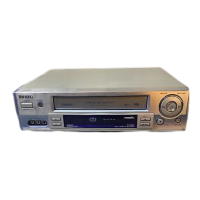
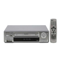
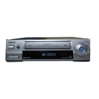
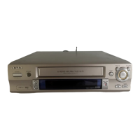
Identifies the Aiwa HV-FX7800 and HV-FX4300 models.
Detailed specifications for the HV-FX7800 Stereo Video Cassette Recorder.
Detailed specifications for the HV-FX4300 Video Cassette Recorder.
Lists part numbers and descriptions for included accessories.
Steps for removing the top case and front panel.
Instructions for removing the mechanism and main circuit board.
Procedure for setting the mechanism to a stable service position.
Table detailing test tape models, contents, and applications.
List of integrated circuits (ICs) used in the unit.
List of transistors and diodes used in the unit.
List of capacitors on the Main Circuit Board.
List of connectors, switches, and other electronic components.
Lists various switches and connector assemblies.
Illustrations showing common transistor types and their E-C-B pinouts.
Diagram showing wire harness connections between boards and components.
Block diagram illustrating the power supply section and its interconnections.
Block diagram for the audio and video processing for the HV-FX7800 model.
Block diagram for the audio and video processing for the HV-FX4300 model.
Block diagrams detailing the video signal processing circuits.
Block diagrams illustrating the normal audio signal processing.
Block diagrams for the tuner and NICAM/A2 audio sections.
Block diagrams for system control, servo, and OSD functions.
Block diagrams for system control, servo, and OSD functions.
Detailed schematics for the power, tuner, and NICAM sections.
Detailed schematics for the power and tuner sections of the HV-FX4300.
Voltage chart for power and NICAM sections, including IC and transistor readings.
Voltage chart for audio and video sections, including IC and transistor readings.
Illustrates various audio and video signal waveforms from IC301.
Detailed schematic for the audio and video circuit board.
Schematics for the Hi-Fi audio and SCART connections for HV-FX7800.
Schematics for the SCART connections for HV-FX4300.
Voltage chart for Hi-Fi audio and SCART sections (IC801, IC901).
Schematics for the system control, servo, and OSD sections for HV-FX7800.
Schematics for the system control, servo, and OSD sections for HV-FX4300.
Voltage chart for system control, servo, and OSD sections (IC501, IC502, etc.).
Illustrates waveforms related to system control, servo, and OSD functions.
Pin assignment details for the FL display on the HV-FX7800 model.
Pin assignment details for the LED display on the HV-FX4300 model.
Wiring diagram for the main circuit board of the HV-FX7800 model.
Wiring diagram for the main circuit board of the HV-FX4300 model.
Wiring diagram for the NICAM/A2 circuit board.
Schematics for the Key-1 circuit board of the HV-7800 model.
Wiring diagram for the Key-1 circuit board of the HV-FX7800 model.
Schematics for the Key-1 circuit board of the HV-4300 model.
Wiring diagram for the Key-1 circuit board of the HV-FX4300 model.
Schematics for the Key-2 circuit board.
Wiring diagram for the Key-2 circuit board.
Lists required test equipment and adjustment location.
Procedure for performing PG adjustment on the servo system.
Block diagrams for ICs like LC74793, FAN8082, LA71598HM, TDA9605H, STR-G6351L, MM1443XJ.
Details pin functions for IC HD6432197A37FX, pins 1-42.
Details pin functions for IC HD6432197A37FX, pins 43-83.
Details pin functions for IC HD6432197A37FX, pins 84-112.
Pin functions for IC HD6432197A37FX on HV-FX4300, pins 1-41.
Pin functions for IC HD6432197A37FX on HV-FX4300, pins 42-82.
Pin functions for IC HD6432197A37FX on HV-FX4300, pins 83-112.
Pin functions for the MSP3417D-QG IC.
Pin functions for the LC74793 IC.
Diagnostic steps for when the 5.3VA power supply is missing.
Diagnostic steps for when the 12VA supply to the capstan is missing.
Diagnostic steps for when the 12VT supply is missing.
Steps for diagnosing unstable video during playback.
Diagnostic steps for when the 5VT (5V) supply is missing.
Steps for diagnosing a missing display on Hi-Fi models.
Diagnostic steps for a stopped capstan motor.
Diagnostic steps for a stopped drum motor.
Steps for diagnosing unstable cassette tape loading.
Diagnostic steps for function buttons that do not work.
Diagnostic steps for missing Y (luminance) signal during playback.
Diagnostic steps for the auto stop function.
Diagnostic steps for no video signal in EE mode.
Diagnostic steps for missing C (color) signal during playback.
Diagnostic steps for no video signal during recording.
Steps for diagnosing no picture on the TV screen.
Diagnostic steps for no sound on mono models.
Diagnostic steps for no sound on Hi-Fi models.
Diagnostic steps for no sound during Hi-Fi playback.
Diagnostic steps for issues with Hi-Fi recording and playback.
Exploded view showing the main mechanical components and assemblies.
List of main mechanical parts with part numbers and descriptions.
Table mapping basic color symbols to their corresponding color names.
Detailed exploded views of specific mechanism sub-assemblies.
List of specific mechanical parts with part numbers.
Further detailed exploded views of mechanism sub-assemblies.
List of mechanical parts, including motors and gears.
Final set of exploded views for mechanism sub-assemblies.
Listing of various mechanical parts like gears, springs, and levers.
Diagrams showing part locations on the top view of the deck mechanism.
Diagrams showing part locations on the bottom view of the deck mechanism.
Step-by-step instructions for disassembling the drum assembly.
Instructions for disassembling plate, holder, arm, and lever assemblies.
Steps for disassembling bracket, guide, and arm assemblies.
Instructions for disassembling the arm cleaner and head F/E.
Steps for disassembling the base assembly for the A/C head.
Instructions for disassembling brake and arm assemblies.
Procedure for removing the Reel S and Reel T.
Steps for disassembling support, base, and opener lid components.
Instructions for disassembling arm assembly T/up and pinch.
Instructions for disassembling belt, motor, and clutch assemblies.
Steps for disassembling lever F/R and gear assemblies.
Instructions for disassembling bracket jog and rack F/L.
Steps for disassembling the brake assembly for the capstan.
Instructions for disassembling gear drive, cam, and connector.
Steps for disassembling the bracket assembly for the L/D motor.
Instructions for disassembling gear sector, base tension, and plate slider.
Steps for disassembling the lever tension mechanism.
Instructions for disassembling gear and base assemblies.
Steps for disassembling the arm assembly idler.
Lists required tools such as torque meters and alignment tapes.
Table detailing alignment tape types and their applications.
Procedure to check and set the mechanism alignment position.
Steps to set the mechanism to the loading state without a cassette.
Procedure and values for checking tape transport torque.
Initial adjustment of guide roller height for proper tape path.
Detailed adjustment of guide roller height using waveforms.
Initial adjustment of A/C head height and tilt for tape path accuracy.
Ensuring smooth tape path and precise azimuth adjustment.
Steps for adjusting the X-value for VCR compatibility.
Procedures for roller guide and X-value adjustment after drum replacement.
Ensuring smooth tape travel and checking for jamming.
Initial checks for common faults like color beats and low volume.
Guidelines for periodic inspection and maintenance schedules.
Lists cleaning materials and provides steps for cleaning heads and transport.
Instructions on applying grease to specific points of the mechanism.
Diagnostic steps for when the auto rewind function does not work.
Diagnostic steps for when F/R modes are not functioning.
Diagnostic steps for the auto stop function during play/cue/rev.
Steps for diagnosing issues with cassette loading.
Diagnostic steps when tape presence is not sensed in playback mode.
Steps for diagnosing issues when a cassette cannot be inserted.
Diagnostic steps for when the cassette will not eject.
Steps for diagnosing issues when a cassette will not load.