EasyManua.ls Logo

Aiwa NSX-AJ503 User Manual

Aiwa NSX-AJ503
83 pages
To Next Page IconTo Next Page
Page #1 background imageLoading...
Page #1 background image
SERVICE MANUAL
DATA
NSX-AJ500
NSX-SZ500
NSX-AJ503
U
LH,EZ
U
SIMPLE
S/M Code No. 09-011-440-6T1
Replace this Service manual with “Revision Publishing” when it is issued.
COMPACT DISC STEREO SYSTEM
BASIC TAPE MECHANISM: ZZM-3 PR1NF
BASIC CD MECHANISM: BZG-5 YKZD3NF
w
w
w
.
x
i
a
o
y
u
1
6
3
.
c
o
m
Q
Q
3
7
6
3
1
5
1
5
0
9
9
2
8
9
4
2
9
8
T
E
L
1
3
9
4
2
2
9
6
5
1
3
9
9
2
8
9
4
2
9
8
0
5
1
5
1
3
6
7
3
Q
Q
TEL 13942296513 QQ 376315150 892498299
http://www.xiaoyu163.com
Question and Answer IconNeed help?

Do you have a question about the Aiwa NSX-AJ503 and is the answer not in the manual?

Aiwa NSX-AJ503 Specifications

General IconGeneral
BrandAiwa
ModelNSX-AJ503
CategoryStereo System
LanguageEnglish

Summary

Aiwa NSX Series Service Manual Introduction

Supported Product Models and System Type

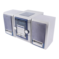
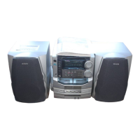
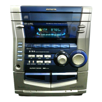
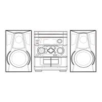
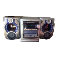
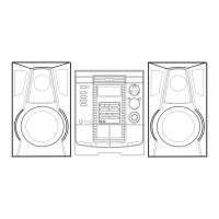
Identifies Aiwa stereo models NSX-AJ500, NSX-SZ500, NSX-AJ503 and system type.

Key Mechanisms and Revision Notes

Details basic tape/CD mechanisms and revision publication instructions.

Schematic Diagrams

Schematic Diagram 1: Main Unit 500U

Circuit diagram for the main unit of the NSX-AJ500 model.

Schematic Diagram 2: Main Unit 503U

Circuit diagram for the main unit of the NSX-AJ503 model.

Schematic Diagram 3: Main Unit LH

Circuit diagram for the main unit, LH variant.

Schematic Diagram 4: Main Unit EZ

Circuit diagram for the main unit, EZ variant.

Schematic Diagram 5: Tuner Unit U

Circuit diagram for the tuner unit, U variant.

Schematic Diagram 6: Tuner Unit LH

Circuit diagram for the tuner unit, LH variant.

Schematic Diagram 7: Tuner Unit EZ

Circuit diagram for the tuner unit, EZ variant.

Schematic Diagram 8: Front Section U

Circuit diagram for the front section, U variant.

Schematic Diagram 9: Front Section LH

Circuit diagram for the front section, LH variant.

Schematic Diagram 10: Front Section EZ

Circuit diagram for the front section, EZ variant.

Schematic Diagram 11: Power Transformer Unit U

Circuit diagram for the power transformer unit, U variant.

Schematic Diagram 12: Power Transformer Unit LH

Circuit diagram for the power transformer unit, LH variant.

Schematic Diagram 13: Power Transformer Unit EZ

Circuit diagram for the power transformer unit, EZ variant.

Manufacturer Information

AIWA CO.,LTD. Contact Details

Provides company name, address, and contact telephone number.

Related product manuals