Do you have a question about the Aiwa NSX-BL44 G and is the answer not in the manual?
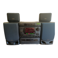
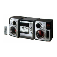
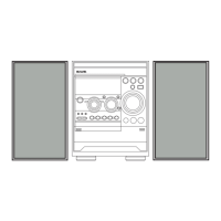
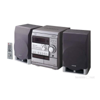
Details the main unit's technical specifications and features.
Covers technical details for FM, AM, and LW tuner sections.
Details amplifier output and cassette deck technical parameters.
Provides CD player specifications and general operational parameters.
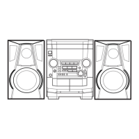
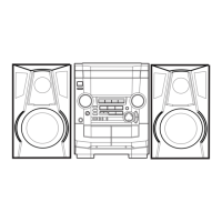
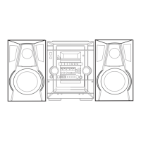
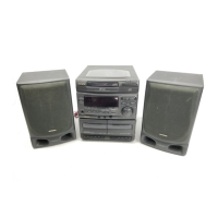
Details the technical specifications for the SX-NBL40, SX-NBL42, SX-NSZ53 speaker systems.
Provides essential warnings and precautions for protecting eyes from laser radiation.
Outlines necessary steps and precautions for safely replacing the optical block.
Explains the procedure for safely discharging electrolytic capacitors before starting repairs.
Details checks required before replacing the microcomputer, including HOLD terminal status.
Describes how to perform a forced reset on the microcomputer to check its functionality.
Details how to check the soldering quality of the microcomputer for proper operation.
Lists integrated circuits used in the main unit with part numbers and descriptions.
Lists transistors used in the main unit with part numbers and descriptions.
Lists diodes used in the main unit with part numbers and descriptions.
Lists components specific to the main circuit board with part numbers.
Lists components found on the Deck Circuit Board (C.B).
Lists components found on the Head-1 Circuit Board (C.B).
Lists components found on the PT Circuit Board (C.B).
Explains the system used for coding chip resistors and their values.
Illustrates the pin configurations for various transistors used in the equipment.
Details the pin assignments for the FL (HNA-11MM30) connector grids.
Details the anode connection assignments for various connectors and boards.
Schematics for Main C.B. function and amplifier sections.
Schematics for the Main C.B. tuner section.
Illustrates the wiring connections for the Main Circuit Board.
Schematics and wiring for PT and Deck Circuit Boards.
Illustrates the wiring connections for the Front Circuit Board.
Diagrams showing the internal blocks of key integrated circuits.
Details the pin functions and descriptions for the LC866560W and LC866548V integrated circuits.
Covers adjustments for the Main Circuit Board, including tuner and AM IF sections.
Details adjustment procedures for Deck 1 and Deck 2 mechanisms, including tape speed and azimuth.
Describes the adjustment procedure for the µ-CON OSC on the Front Circuit Board.
Provides a detailed exploded view of the CD mechanism (AZG-1).
Provides a detailed exploded view of the tape mechanism (6ZM-3).
Lists mechanical parts for the chassis, windows, panels, and covers.
Lists mechanical parts like knobs, springs, levers, and mechanism components.
Lists parts for the 6ZM-3 PR2NM (44/46) and 6ZM-3 YPR2N (DR6) tape mechanisms.
Provides exploded views of the 6ZM-3 PR2NM and 6ZM-3 YPR2N tape mechanisms.
Provides instructions on how to disassemble speaker units.
Lists the parts for various speaker models.
| Brand | Aiwa |
|---|---|
| Model | NSX-BL44 G |
| Category | Stereo System |
| CD Player | Yes |
| Remote Control | Yes |
| Speakers quantity | 2 |
| Type | Mini Hi-Fi System |
| Cassette Deck | Yes |
| Radio | AM/FM |
| Connectivity | Auxiliary input |
| Functions | CD, Radio, Cassette |