Do you have a question about the Aiwa NSX-R11 and is the answer not in the manual?
Precautions for replacing the optical block to prevent electrostatic discharge and laser exposure.
Procedure to safely discharge electrolytic capacitors in the power supply before servicing.
Check the HOLD terminal voltage of the microcomputer to diagnose issues.
Procedure for forced-resetting the microcomputer to diagnose issues.
Checking the microcomputer's soldering state to rule out poor connections as a cause of failure.
Procedures for adjusting tuner VT and clock settings for optimal reception.
Procedure to check the tuner clock frequency using a frequency counter.
Adjusting MW and LW IF and tracking for accurate signal reception.
Checking the auto-stop function for MW tuning search mode.
Procedures for tracking adjustment and auto-stop function check for FM.
Procedures for tape speed, wow-flutter, azimuth, and frequency response adjustments.
Checking playback sensitivity of DECK 1 and DECK 2.
Adjusting record/playback frequency response for Deck 2.
Checking record/playback sensitivity for Deck 2.
Procedure for adjusting the clock in the front section.
| Brand | Aiwa |
|---|---|
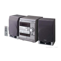
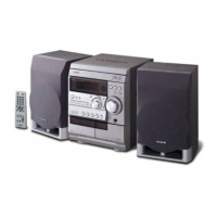
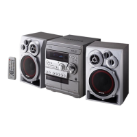
| Model | NSX-R11 |
| Category | Stereo System |
| Language | English |