EasyManua.ls Logo

Aiwa NSX-R70 User Manual

Aiwa NSX-R70
58 pages
To Next Page IconTo Next Page
Page #1 background imageLoading...
Page #1 background image
SERVICE MANUAL
DATA
NSX-R70
LH(S)
S/M Code No. 09-024-452-3R2
BASIC TAPE MECHANISM : 2ZM-3MK2 PR7NM
BASIC CD MECHANISM : BZG-5 ZD5GNM
This Service Manual is the “Revision Publishing” and replaces “Simple Manual”,
NSX-R70 LH(S), S/M Code No. 09-022-452-3T2.
If requiring information about the CD mechanism, see Service Manual of BZG-5,
(S/M Code No. 09-023-353-3NC)
REVISION
CX–NR70NSX-R70 RC–CAS01
SYSTEM
CD
CASSEIVER
REMOTE
CONTROLLER
SPEAKER
SX–NR70
CD STEREO SYSTEM
w
w
w
.
x
i
a
o
y
u
1
6
3
.
c
o
m
Q
Q
3
7
6
3
1
5
1
5
0
9
9
2
8
9
4
2
9
8
T
E
L
1
3
9
4
2
2
9
6
5
1
3
9
9
2
8
9
4
2
9
8
0
5
1
5
1
3
6
7
3
Q
Q
TEL 13942296513 QQ 376315150 892498299
http://www.xiaoyu163.com
Question and Answer IconNeed help?

Do you have a question about the Aiwa NSX-R70 and is the answer not in the manual?

Aiwa NSX-R70 Specifications

General IconGeneral
CD PlayerYes
Remote ControlYes
Cassette DeckYes
Output Power30W per channel
Speakers Configuration2-way, 2 speakers

Summary

Specifications

FM, AM, Amplifier, and Speaker Details

Detailed specifications for FM/AM tuners, amplifier, speakers, and general system parameters.

Safety and Pre-Repair Procedures

Laser Safety and Optical Block Precautions

Instructions to prevent eye exposure to laser and safe optical block replacement.

Capacitor Discharge and Microcomputer Checks

Procedures for capacitor discharge and microcomputer functional verification.

Circuit Schematics and Wiring

Main Circuit Schematic Diagram

Main circuit schematic diagram (1/4).

Tuner Section Schematic Diagram

Circuit schematic for the tuner section (2/4).

Power Transformer Schematic Diagram

Circuit schematic for the power transformer section.

Deck and Head Unit Wiring

Wiring diagrams for deck and head units.

IC Information

Key IC Block Diagrams

Functional block diagrams for major integrated circuits.

µPD780226GF-030-3BA IC Description

Pin assignments and descriptions for the µPD780226GF-030-3BA IC.

Adjustment and Test Procedures

Tuner, AM, and FM Adjustments

Procedures for tuning AM/FM sections and clock check.

Deck Adjustments and CD Test Mode

Procedures for deck adjustments.

CD Test Mode Functions

Procedures and functions for operating the CD player in test mode.

Parts Lists and Mechanical Views

Electrical Parts List

List of electrical components for the CX-SNR70 system.

Mechanical Parts List

List of all mechanical parts with their reference numbers.

Tape Mechanism Parts List

List of parts for the tape mechanism.

Mechanical Exploded View

Illustrated breakdown of the unit's mechanical components.

Tape Mechanism Exploded View

Illustrated breakdown of the tape mechanism.
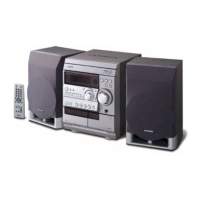
Related product manuals