EasyManua.ls Logo

Aiwa NSX-R51 User Manual

Aiwa NSX-R51
39 pages
To Next Page IconTo Next Page
Page #1 background imageLoading...
Page #1 background image
SERVICE MANUAL
DATA
COMPACT DISC
STEREO SYSTEM
BASIC TAPE MECHANISM : ZZM-3 PR3NM
BASIC CD MECHANISM : BZG-5 ZD3GNM
NSX-R50
NSX-R51
K
EZ
S/M Code No. 09-01A-449-7N1
• If requiring information about the CD mechanism, see Service Manual of
BZG-5, (S/M Code No. 09-00C-353-3N6).
SPEAKERSYSTEM
CX-NR50
RC-CAS01
CD
CASSEIVER
REMOTE
CONTROLLER
SX-NR50
NSX-R50
NSX-R51 CX-NR51
All manuals and user guides at all-guides.com
all-guides.com
Question and Answer IconNeed help?

Do you have a question about the Aiwa NSX-R51 and is the answer not in the manual?

Aiwa NSX-R51 Specifications

General IconGeneral
TypeStereo System
CD PlayerYes
Cassette DeckYes
Radio TunerYes
Cassette Deck TypeDual Cassette Deck
Remote ControlYes
EqualizerYes
Speakers2-way speakers
FunctionsCD, Radio, Cassette
Weight5.5 kg
Power Output50W (25W per channel)

Summary

Product Specifications

Laser Safety During Servicing

Warnings and Precautions

Safety warnings, cautions, and advisories regarding laser beam exposure during servicing procedures.

Optical Block Replacement Precautions

Specific precautions related to handling and replacing the optical block to prevent damage and ensure safety.

Pre-Repair Procedures

Electrolytic Capacitor Discharge

Procedure for safely discharging electrolytic capacitors in the power supply block before repair.

Microcomputer Reset and Soldering Checks

Reset Procedure

Procedure for performing a forced reset on the microcomputer to check its functionality.

Wiring Diagrams

Main Schematic Diagram 1

Main C.B Schematic (1/2)

First part of the schematic diagram for the Main Circuit Board.

Main Schematic Diagram 2

Main C.B Schematic (2/2: Tuner)

Second part of the schematic diagram for the Main Circuit Board, focusing on the tuner section.

HP Schematic Diagram 3

HP C.B Schematic

Schematic diagram for the Headphone (HP) Circuit Board.

Front and LED Wiring Diagram

Front, LED, and Deck Schematic Diagram 4

Front C.B, LED C.B, and Deck C.B Schematics

Schematic diagrams for the Front, LED, and Deck Circuit Boards.

Power Transformer Wiring Diagram

Power Transformer Schematic Diagram 5

PT C.B Schematic

Schematic diagram for the Power Transformer (PT) Circuit Board.

Deck Wiring Diagram 4

IC Block Diagrams Overview

Adjustment Procedures

Main C.B Adjustment Points

Identification of adjustment points on the Main Circuit Board (C.B).

Deck C.B Adjustment Points

Identification of adjustment points on the Deck Circuit Board (C.B).

Tuner Adjustments

VT and Frequency Checks

Procedures for checking VT levels and frequencies for LW, MW, and FM bands.

MW/LW Alignment and Checks

IF and Tracking Adjustments

Alignment procedures for Intermediate Frequency (IF) and tracking in MW/LW bands.

FM Alignment and Checks

Tracking Adjustment and Separation Check

Alignment for tracking and checking signal separation in FM band.

Deck Section Adjustments

Tape Speed and Wow-Flutter Checks

Procedures for checking tape speed accuracy and wow-flutter levels for both decks.

Head Azimuth Adjustment

Procedure for adjusting the head azimuth for optimal playback in both decks.

Playback Frequency and Sensitivity Checks

Checks for playback frequency response and sensitivity levels for both decks.
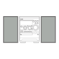
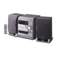
Deck Playback/Record Performance

Front Section Clock Adjustment

CD Test Mode Operations

Mechanical Exploded View

Tape Mechanism Exploded View

Speaker Disassembly Instructions

Related product manuals